Center of Light Manipulations and Applications & Shandong Provincial Key Laboratory of Optics and Photonic Device,School of Physics and Electronics,Shandong Normal University,Jinan 250358,China
Doped LiNbO3 crystal is one kind of photorefractive mediums which are used for optical storage. When light passes through LiNbO3 crystal, it will cause local refractive index change and form noise grating. The noise grating diffracts the incident light, transferring part of the light energy to the scattered light, namely, light-induced scattering. In recent years, the modulation instability, generation process and energy transfer efficiency of light scattering in LiNbO3 crystals have been widely studied. Since a single component of linearly polarized light is used for the incident, no variation of the polarization state of the outgoing light is observed. However, considering the difference of energy transmission efficiency between o-light and e-light, it is reasonable to guess that the polarization state of the outgoing light may change when another light is incident. According to our investigation, there is no research in this field. In this work, the variation of the polarization state of LiNbO3:Fe crystal during the light-induced scattering process is reported. The circularly polarized light is focused into a thin light sheet and irradiated on the crystal with the c-axis along the vertical direction. The light scattering phenomenon at different incident angles is studied. In the tens of minutes from the generation of the scattered light to the steady state, the scattered light mainly grows in the direction parallel to the c-axis, and there is also a component in the direction parallel to the light sheet. The growth rate of scattered light decreases with the increase of the incident angle. Further observation manifests that the circularly polarized light becomes ordinary elliptically polarized light after passing through the crystal, and the ellipticity varies with the incident angle. Combined with the noise grating formed in the crystal, the scattering model of circularly polarized light is established, and the reason and mechanism of polarization state change are analyzed through calculation. Qualitative analysis shows that the ellipticity of scattered light is related to the transmission coefficient and azimuth angle, and the left-handed or right-handed polarization state is also related to the phase difference between o-light and e-light. This discovery proposes a method to generate elliptically polarized light using the light-induced light-scattering properties of photorefractive crystals, which can be applied to optical storage and photonic lattice based on photorefractive materials.
The lithium niobate(LiNbO3)crystal is a negative uniaxial crystal(no>ne). BAUMAN A was the first to use the Czochralski technology to grow large-volume lithium niobate crystals in 1965. Since then,the properties of lithium niobate crystals have been widely studied and the crystals have been used for various applications[1]. In 1966,ASHKIN A et al[2] used LiNbO3 and LiTaO3 crystals to perform frequency doubling experiments and found that the refractive index of the irradiated region changed,namely,"optical damage" .This kind of damage can be eliminated by high temperature heating. To distinguish it from permanent damage,this effect is referred to as photoinduced refractive index change or photorefractive effect which has been widely used in optical information storage[3-4].
As a photorefractive material,the LiNbO3 crystals have a variety of intrinsic defects[5]. When light enters the crystal,the intrinsic defects scatter the incident light. The scattered light interferes with the incident light,creating a grating structure inside the crystal[6] which is regarded as noise grating. The incident light transmits part of the energy to the scattered light through diffraction by the noise grating. As a result,the scattered light gradually increases until it is stable. This phenomenon of light amplification,caused by the photorefractive effect,is called light-induced scattering[7]. The in-depth study of LiNbO3 crystals resulted in the findings that the photorefractive effect of pure LiNbO3 crystals is weak and that doping by certain metal ions can improve its photorefractive performance[8-9]. For example,in iron-doped LiNbO3 crystals,the valence states of Fe2+ and Fe3+ ions are mutually transformed,which supports the "excitation-capture-re-excitation-re-capture" process of charge carriers,thereby enhancing the photorefractive effect of the crystal[10].
In recent years,the light-induced scattering phenomena of photorefractive crystals have been extensively studied[11-23]. LIN Rong et al[24-26] studied the modulation instability and its influencing factors in LiNbO3:Fe crystals. ZHANG Yan and GAO Yuanmei et al[27-28] observed the scattering phenomenon of a focused beam incident on the LiNbO3:Fe crystal and found that the scattered light grew mainly along the direction of the incident beam. LU Chengzhen et al. [29] studied the scattering phenomena of e-light and o-light and their Energy Transfer Efficiency(ETE)and found that the ETE of o-light is higher than that of e-light. Since a single component of linearly polarized light is used for the incident,no variation of the polarization state of the outgoing light is observed. However,considering the difference in ETE between o-light and e-light,one has reason to guess that when another kind of light is incident,what's different from the outgoing light?According to our investigation,there is no research on this aspect at present.
In this work,we studied multiple groups of light-induced scattering phenomena in iron-doped LiNbO3 crystal with different incident directions of circularly polarized light. After the scattered light was stabilized,we observed the noise grating in the crystal. Then,the polarization state of the light emitted after the crystal was checked by the light energy measurement along two orthogonal axes in the transverse direction. Simultaneously,the ellipticity of the light was calculated.
1 Experimental setup
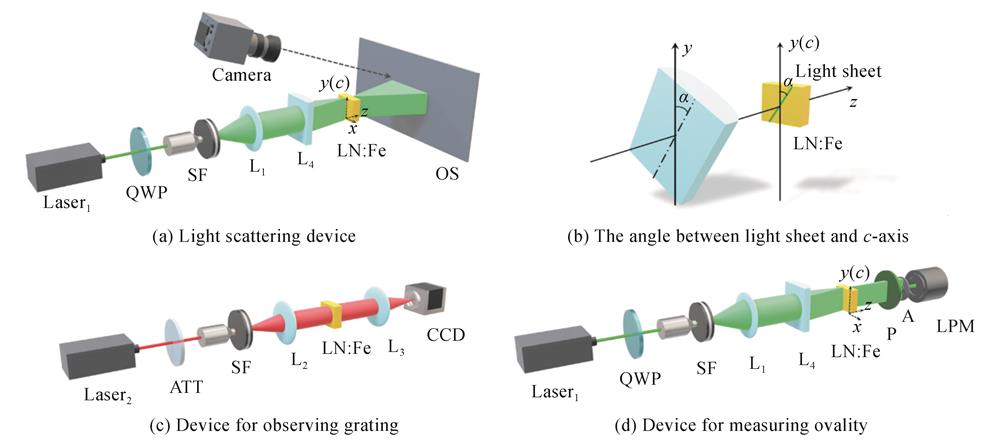
The apparatus shown in Fig. 1(a)is used to observe the scattering phenomena of the LiNbO3:Fe crystal(0.03 wt% Fe,10 mm×5 mm×10 mm). The c-axis of the crystal is along the y-direction. The laser1 outputs linearly polarized light polarized in the vertical direction,with a power of 200 mW and a wavelength of 532 nm. A Quarter Wave Plate(QWP),a Spatial Filter(SF),a convex lens(L1)and a cylindrical lens(L4)form a beam shaping system. The beam passes through the shaping system to become a band-shaped beam(light sheet),which then irradiates the crystal. The far-field scattering image appears on the Optical Screen(OS). When the collimated parallel light is irradiated onto the cylindrical lens,due to the unidirectional focusing character of the cylindrical lens,the light beam can be focused to be a sheet in a certain direction at the focal point,then expanding in this direction. That's why the light sheet on the screen rotates 90° relative to the light sheet incident on the crystal. The cylindrical lens is rotated so that the angles(between the incident light sheet and the c-axis of the crystal)are altered as α=0°,30°,45°,60°,and 90° relative to the y-axis,as shown in Fig. 1(b). The scattering image was recorded using a camera(Canon EOS 70D).
Figure 1.Experimental setup and light path diagram
The device shown in Fig. 1(c)was used to observe the noise grating in the LiNbO3:Fe crystal. The laser passing through the attenuator(ATT)passes through the SF and the lens(L2),irradiates on the crystal,and then images through the lens(L3). The raster information is captured by the Charge Coupled Device(CCD)and displayed on the computer screen. The laser 2 outputs linearly polarized light polarized in the vertical direction,with a power of 50 mW and a wavelength of 632 nm. Laser 1 has high coherence and will produce more noise when used as readout light to disturb the original grating pattern. Therefore,laser 2 with low coherence and low power is selected to avoid disturbing the grating pattern.
The device shown in Fig. 1(d)is used to determine the polarization state of the light after passing through the crystal. The scattered light passes through the polarizer(P)and the aperture(A,with a diameter of 4 mm)in turn and is received by the Laser Power Meter(LPM). The aim is achieved by rotating the polarizer and recording the maximum power()and the minimum power()by the LPM. The intensity of the scattered light located in the scattering areas on both sides is much less than the central light intensity. The comparison between and is not obvious,and the measurement error is large. Therefore,the polarization state of the scattered light in the central area is measured. The ellipticity is usually expressed by the ratio of the semi-major axis to the semi-minor axis,so the ellipticity of the beam can be calculated by the following formula
where and are the amplitudes of semi-minor axis and semi-major axis respectively,and and are the corresponding light intensity.
2 Experimental results
2.1 Light scattering results under different configurations
The light-induced scattering phenomenon of LiNbO3:Fe crystal has a strong regularity. An image is taken every 5 s and choose five of them for each polarization angle. The light scattering patterns at five angles are shown in Fig. 2,where c represents the c-axis and f represents the light sheet direction. The light distribution on the screen showed that the scattered light was rapidly generated in a few minutes and the scattered light was not continuous,but consists of closely spaced filaments paralleling to the light sheet,and the filaments extend with the growth of the scattered light,as shown in the white dashed box in Fig. 2(a). The growth of the scattered light is not only perpendicular to the light sheet beam but also presents along the light sheet beam. As shown in Fig. 2(a)~(e),it is clear that the length of the light sheet on the screen increases with the angle,indicating that the incident light energy has been transmitted in two perpendicular directions. However,the light scattering laws under the five configurations are not completely identical. When α=0 is set,the scattered light grows rapidly to both sides with the incident beam as the center,and the growth direction is parallel to the c-axis of the crystal,that is,parallel to the incident light sheet,as shown in Fig. 2(a). The angle between the strip beam and the crystal c-axis was adjusted to 30°,45°,and 60° respectively,and the light scattering results are shown in Fig. 2(b),(c)and(d). The scattered light exists not only in the direction parallel to the light sheet but also in the direction parallel to the c-axis of the crystal. Moreover,with the increase of angle α,the scattered light component perpendicular to the light sheet also increases. When α is 90°,the scattered light mainly intensifies along the direction parallel to the c-axis,that is,perpendicular to the direction of the light sheet. But there is a component in the direction perpendicular to the light sheet. When α is set to 0 or 90°,the scattering pattern is axisymmetric,while at other angles,the scattering pattern is not axisymmetric. This is because the scattering component extending along the f-direction is affected by the nonlinearity of the c-axis direction,and the whole scattering pattern extends along the positive and negative c-axis direction,resulting in the non-axisymmetric diffraction pattern. In addition,the speed of scattered light growth is different for various angles α. The time taken to reach a steady state in Fig. 2(a),(b),(c),(d),and(e)is 10 min,20 min,30 min,50 min,and 70 min,respectively. The scattering law can be obtained:the light scattering is mainly concentrated in the direction parallel to the c-axis. When there is a certain angle between the incident light direction and the c-axis direction,there is a component of the scattered light in the direction perpendicular to the light sheet. The smaller the angle between the incident light sheet and c-axis,the faster it reaches the steady state.
Figure 2.Scattered light at α=0,30°,45°,60° and 90° respectively
After the scattered light reaches the steady state,the noise grating inside the crystal is observed using the device of Fig. 1(c). The 30°,45°,60°,and 90° noise gratings are the composition of two chirped gratings,as shown in Fig. 3(a)~(d). It can be seen that the grating appears as dense straight stripes,and the stripes direction is the same as the growth direction of the scattered light. However,the gratings are not uniform,and the densities of the gratings increase from the middle to the sides. The reason is that the focused beam has “self-defocusing” in the crystal. It is necessary to observe the distribution of noise grating for the next study of the mechanism of light-induced scattering.
Figure 3.Noise grating in the crystal at different incident angles
2.2 Measurement of the polarization state of scattered light
The polarization state of the output light is measured by the device shown in Fig. 1(d)and characterized by ellipticity. Through Eq.(1),the polarization states at the center of the outgoing light at different incident angles are calculated. It is found that the circularly polarized light becomes elliptically polarized light after passing through the crystal. The ellipticities are measured several times and the averages are shown in Fig. 4. When the incident angle α=30° or 45°,the emitted light is close to the circularly polarized light,and at other incident angles,the emitted light is elliptically polarized light significantly.
Figure 4.Polarization state of outgoing light at different incident angles
When the beam irradiates the LiNbO3:Fe crystal,light scattering of nearly 90° was observed,and light scattering crawling along the crystal optical axis direction in the crystal was detected as well[30],as shown in Fig. 5. This experiment proved that this type of crawling light scattering causes energy dissipation. The energy of the scattered light leaks from the crystal during the crawling process is the energy source of the light scattered at nearly 90°. Taking α=90° as an example,Fig. 5(a),(b)show the angle of the incident of the light sheet,and Fig. 5(c)shows the light crawling model,and the scattered light on the optical screen is shown in Fig. 5(d). When the crystal is irradiated,only the forward-scattered light with a wide scattering angle can travel a long distance in the irradiation area,thus passing through the noise grating and obtaining more energy from the incident light. Scattered light with a wide reflection angle may pass through multiple reflections in the irradiated area and obtain effective amplification. The light with a small scattering angle directly passes through the crystal without grating,which makes little contribution to the scattered light. During crawling,scattering also results in local refractive index changes in the crystal,which in turn causes the scattered light to be produced continuously. Light and dark parallel stripes can be seen in the light crawling area and are stored in the crystal,as shown in Fig. 3. This qualitatively explains why the scattered light is composed of closely arranged filaments and the formation process of the chirped grating.
Figure 5.Light crawling and light scattering model
The incident light beam forms a grating in the crystal as shown in Fig. 3,and the grating expands to both sides with the light beam as the center. The grating diffracts continuous light,i.e. light-induced self-diffraction[31-32]. Light-induced light scattering and light-induced self-diffraction are competing processes. When the direction of the light stripe is the same as the direction of the crystal c-axis,light-induced self-diffraction and light-induced light scattering occur at the same time. The process by which incident light transfers energy. When the included angle is 30°,45°,or 60°,it takes a certain time(time for light scattering to reach saturation)to form the phase grating. At the beginning,the phenomenon of "light overflow" occurs in the direction perpendicular to the beam,that is,at this time,light-induced self-diffraction dominates,and more energy is obtained from the incident light. However,as light-induced light scattering gradually dominates the competition,the energy of incident light is eventually transferred to light-induced light scattering. Therefore,light-induced light scattering still plays a major role in the scattering effect. When the included angle is 90°,the photorefractive effect is the weakest,the scattering phenomenon is not easy to observe,and the energy transferred from the incident light is the least. In addition,in the sub-beam passing region,electrons are excited to form electron-hole pairs. Electrons and holes are two types of scattering sources for incident light. Under continuous illumination,when the concentration of the scattering sources in the illumination area is balanced,the light scattering reaches a steady state.
3.2 Analysis of polarization state change
We establish the scattering model of the crystal to the circularly polarized light to analyze the polarization state of the scattered light,as shown in Fig. 6. The circularly polarized light propagating along the z-axis is focused by a cylindrical lens into a narrow light sheet f. the angles between the scattered light and the x-axis and y-axis are and ,respectively. The electric field vector expression of circularly polarized light is
Figure 6.The model of polarization state change of scattered light
where E is the electric field vector,A0 is the amplitude of the component in the x or y direction,and ex,ey are the unit vectors along the x and y-axis. Let the electric field components of the emitted light in x,y-axis be Ex,Ey,then
is the phase difference between e-light and o-light caused by crystal. Let
then
assuming ,the ellipticity of scattered light can be expressed as
It can be seen from Eq.(6) that the ellipticity of scattered light is related to the transmission coefficient and azimuth angle,and the left-handed or right-handed polarization state is also related to the phase difference . Because of the anisotropy and photorefractive effect of crystal,it is difficult to calculate its value,but qualitative analysis can be done. The polarization state transition effect of LiNbO3:Fe crystal can be used to obtain elliptically polarized light from circularly polarized light.
4 Conclusion
In summary,the scattering phenomena generated by circularly polarized light irradiating a LiNbO3:Fe crystal was investigated. The scattered light mainly grows in the direction parallel to the c-axis and has a component in the direction parallel to the light sheet,and the growth speed of the scattered light decreases with the increase of the incident angle α. Moreover,circularly polarized light degrades into ordinary elliptically polarized light after passing through the crystal. We use the light crawling model to analyze the generation mechanism of scattered light and noise grating,calculate the ellipticity of the outgoing light,and analyze the cause of polarization state degradation. We establish the scattering model of circularly polarized light and analyze the reason why circularly polarized light degenerates into elliptically polarized light in this process. In addition,this research inspired us to use the light-induced scattering properties of photorefractive crystals to generate elliptically polarized light. The light-induced light-scattering enhances the system noise to a certain extent. This noise will persist and weaken the incident light energy,which causes issues for the applications of photorefractive materials. This work provides a reference for elliptically polarized light generation,optical storage and photonic lattice research,thus leading to the improvement of photorefractive material applications and technologies.
[17] Dean LIU, Liren LIU, Liyong REN et al. Material optimization for low scattering noise during nonvolatile holographic recording in doubly doped LiNbO3 crystals. Chinese Optics Letters, 2, 630-633(2004).