• Journal of Infrared and Millimeter Waves
  • Vol. 40, Issue 1, 33 (2021)
Jie XU1、3、*, Zheng-Bin XU1, Jian GUO1, Cheng QIAN1、**, and Di-Xian ZHAO2、3
Author Affiliations
  • 1State Key Laboratory of Millimeter Waves,Southeast University.Nanjing 210096,China
  • 2National Mobile Communication Research Laboratory,Southeast University,Nanjing 210096,China
  • 3Purple Mountain Laboratories,Nanjing 211111,China
  • show less
    DOI: 10.11972/j.issn.1001-9014.2021.01.006 Cite this Article
    Jie XU, Zheng-Bin XU, Jian GUO, Cheng QIAN, Di-Xian ZHAO. A broadband millimeter-wave sub-harmonic mixer using microstrip passive circuits[J]. Journal of Infrared and Millimeter Waves, 2021, 40(1): 33 Copy Citation Text show less

    Abstract

    This paper presents a millimeter-wave microstrip-based sub-harmonic mixer with a wide operation band. In this design, frequency suppression circuits including a wideband bandpass short-circuited filter and a diplexer are employed not only to provide proper terminations for the intermediate frequency (IF), radio frequency (RF), and local oscillator (LO) signals simultaneously, but also to reject the major idle mixing products. The measured results show that the proposed sub-harmonic mixer can support the operations in RF band from 27 to 48 GHz, and in IF band up to 6 GHz. Meanwhile, the conversion loss is less than 12.5 dB for both up- and down- conversion throughout the bandwidth, in which, the minimum conversion loss is about 7.5 dB and 8.2 dB for the down-conversion and up-conversion, respectively, at an RF of 33 GHz and IF of 1 GHz.

    Introduction

    The sub-harmonic mixer is a common solution in the millimeter-wave system because it only requires a relatively low frequency of local-oscillator(LO)signal,which provides lots of merits,such as high reliability,low phase noise and low cost. Anti-parallel diode pair(APDP)was proved to have several advantages in the design of sub-harmonic mixers12,such as good radio frequency(RF)-to-LO isolation and suppression of any even harmonics of LO signals.

    Many studies have been devoted to the performance improvement of conversion loss of sub-harmonic mixers3-6. Recently,the conversion losses of sub-harmonic mixers achieved similar low level as the fundamental mixers. Meanwhile,different methods are used to improve the operation bandwidth of the sub-harmonic mixers7-14,and the RF bandwidth can be more than one octave. However,it is still difficult to achieve a wide IF bandwidth in design of sub-harmonic mixer.

    In this paper,a millimeter-wave sub-harmonic mixer with a wide IF bandwidth is presented based on standard microstrip hybrid microwave integrated circuit(MIC)technology. Meanwhile,a novel frequency suppression circuit is employed to broaden the bandwidth and decreases the conversion loss. Hence,the proposed sub-harmonic mixer has features of wide operating frequency band,low conversion loss,the ease of fabrication and convenience of integration with microwave and millimeter wave circuits.

    1 Circuit Design

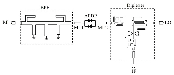
    To achieve broad band,a scheme of APDP sub-harmonic mixer including a short-circuited band pass filter(BPF)and a diplexer is proposed,as shown in Fig. 1. Among them,the BPF can provide a pass band for RF signal and a stop band for LO,IF and some other idle signals of mixing products of IF and LO,located on the left side of APDP. In addition,a diplexer is used to separate the LO and IF signals placed on the right side of APDP.

    The circuit topology of the proposed sub-harmonic mixer

    Figure 1.The circuit topology of the proposed sub-harmonic mixer

    To design such a mixer with low conversion loss and broad band,the key factor is to achieve broad band and low insertion loss of the diplexer,the matching circuits,and the RF filter while maintaining enough isolation between LO and RF.

    Firstly,the diplexer of this work adopts a compact low pass filter(LPF)15 and an improved wideband edge coupled BPF. The wideband edge coupled BPF includes two high impedance open stubs,which are added at both ends of a single section coupled line to reduce the requirement of the lines' width and the gap between the coupled lines. Meanwhile,the diplexer also includes a compact LPF at the common port,which rejects the RF signal and passes the LO and IF signals. The simulation results of the diplexer in HFSS are shown in Fig. 2,in which the common,LO and IF ports are marked as Port 1,2 and 3,respectively. As shown in this figure,the cut-off frequency for the IF is about 6 GHz and the pass-band bandwidth for the LO is about 12 GHz with a center frequency of 18 GHz. The simulation results also show that the diplexer has a sharp rejection level at the stopband.

    Simulated S parameters of the proposed diplexer

    Figure 2.Simulated S parameters of the proposed diplexer

    Secondly,considering to the RF BPF requires high rejection of LO/IF,and low insertion loss at RF port,a broadband BPF using short stubs is chosen for this purpose. Higher-order filter is necessary to achieve higher nearby LO rejection,however higher-order usually leads to higher insertion loss. To overcome this difficulty,a wideband short-circuited BPF shown in Fig. 3(a)is proposed,which consists of a pair of open stubs and three λ/4 shunt shorted stubs that are separated from each other by λ/4 connecting lines. The specific parameters of the filter are optimized by Ansoft HFSS to obtain a transmission zero at lower frequency band to reject the nearby LO signal using the equations in Ref.[16]. Finally,the geometrical parameters is chosen as w1 = 0.65 mm,l1 = 0.6 mm,w2 = 0.54 mm,l2 = 0.9 mm,wp = 0.8 mm,lp = 1.25 mm,wc = 0.15 mm,lc1 = 0.6 mm,lc2 = 2 mm. As shown in Fig. 3(b),the simulated result shown that the pass band is from 26 to 49 GHz,and a sharp rejection level of more than 30 dBc is at around 20 GHz.

    The proposed RF band pass filter (a) Geometry view, (b) Simulated S parameters

    Figure 3.The proposed RF band pass filter (a) Geometry view, (b) Simulated S parameters

    Finally,the APDP used is commercial GaAs Schottky diode DMK2308 from Skyworks,Inc. This diode chip structure can be modeled in HFSS12todetermine the effect of the diode packaging. The input and output matching is achieved by tuning the line width and length of ML1 and ML2. These simple matching circuits help to achieve impedance matching and reduce the overall conversion loss. Hence,the whole completed mixer circuit can be simulated by the harmonic balance analysis module of the Agilent Advanced Design System(ADS). The S-parameters,which represent the frequency response of the passive elements discussed above,are calculated by HFSS and imported to ADS as a “sNp” file. Microstrip lines ML1 and ML2 are added to the circuit to connect those “sNp” modules. And the performance of the mixer is optimized by tuning the lengths of the microstrip lines.

    2 Mixer implementation and performance

    According to the optimized parameters,a demonstration circuit was fabricated on a Duriod RT/5880 substrate with a thickness of 0.254 mm and a relative permittivity of 2.2. And finally the whole mixer is mounted in a metal housing to shield from outside interference,as shown in Fig. 4. Agilent Analog Signal Generator E8257D was used to provide LO signal,and Network Analyzer E8364C was used to measure the frequency response of the mixer.

    Photograph of the fabricated sub-harmonic mixer

    Figure 4.Photograph of the fabricated sub-harmonic mixer

    ReferenceRF frequency /GHz

    IF frequency

    /GHz

    Conversion gain/dBTechnology
    #[8]35 to 42DC to 0.5<-7.2MMIC
    *[9]28 to 50DC to 1-11 to -6.6MMIC
    *[12]90 to 100DC to 4-11 to -8hybrid MIC
    #[13]24 to 441 (fixed)6 to 10.5MMIC
    #*This work27 to 48DC to 6-11.2 to -7.5hybrid MIC

    Table 1. Comparison of reported similar sub-harmonic mixers

    Figure 5(a)illustrates the measured up side band(USB)conversion loss as a function of RF frequency with IF frequency at 1 GHz and 6 GHz,respectively. And all the measurement was implemented with the LO power level at 12 dBm. The minimum conversion loss is about 7.5 dB and 8.2 dB for down-conversion and up-conversion,respectively,at RF of 33 GHz and IF of 1 GHz,and the conversion loss is less than 11.2 dB with IF fixed at 6 GHz for both up-conversion and down-conversion. Meanwhile,Figure 5(b)shows the measured USB and low side band(LSB)conversion loss as a function of RF frequency with IF frequency of 1 GHz. The measured LSB conversion loss presents a sharp rise at the RF frequency of 42 GHz,while the USB conversion loss has little change,which is led by the fact that LO signal is out of range. As the below cut-off frequency of the RF band pass filter is above 26 GHz,both USB and LSB conversion loss increased while the RF frequency below 26 GHz. Measured USB conversion loss versus IF frequency with different LO frequencies is shown in Fig. 6. Down-conversion loss(Fig. 6(a))has a limited difference with the up-conversion loss(Fig. 6(b)). With the increase of IF frequency,the conversion loss increases,especially beyond 6 GHz,that agrees with the performance of the diplexer. In addition,Fig. 7 shows the measurement results of LO-to-RF and LO-to-IF isolations as a function of LO frequency. The LO-to-RF and LO-to-IF isolations are better than 15 and 38 dB for the LO frequency from 13 to 21 GHz,respectively. Hence,the carefully design of pass-band of the BPF and diplexer make it possible to provide a wider IF bandwidth than traditional method.

    Measured conversion loss versus RF frequency at different IF frequencies (a) USB at IF of 1 GHz and 6 GHz (b) USB and LSB at IF of 1 GHz

    Figure 5.Measured conversion loss versus RF frequency at different IF frequencies (a) USB at IF of 1 GHz and 6 GHz (b) USB and LSB at IF of 1 GHz

    Measured USB conversion loss versus IF frequency at different LO frequencies (a) Down-conversion (b) Up-conversion

    Figure 6.Measured USB conversion loss versus IF frequency at different LO frequencies (a) Down-conversion (b) Up-conversion

    Measurement results of LO-to-RF and LO-to-IF isolations as a function of LO frequency

    Figure 7.Measurement results of LO-to-RF and LO-to-IF isolations as a function of LO frequency

    Comparisons between the proposed sub-harmonic mixer and similar published works8-912-13are summarized in Table 1. It shows that the performance of the proposed sub-harmonic mixer is comparable with that of the similar mixers. Moreover,the proposed mixer has a wide IF bandwidth and the microstrip hybrid MIC technology used in this paper has a low cost.

    3 Conclusions

    A microstrip-based millimeter-wave broadband sub-harmonic mixer employing an open stubs loaded short-circuited wideband BPF and a novel diplexer has been proposed. The measured results reveal a conversion loss of 7.5 to 12.5 dB over a wide RF frequency range of 27 to 48 GHz for both up-conversion and down-conversion. This proposed configuration provides a flexible and low-cost design in sub-harmonic mixers,which are relatively efficient for integration of millimeter-wave systems.

    References

    [1] M Cohn, J E Degenford, B A Newman. Harmonic mixing with an antiparallel diode pair. IEEE Trans. Microwave Theory Tech., 23, 667-673(1975).

    [2] A Madjar. A novel general approach for the optimum design of microwave and millimeter wave subharmonic mixers. IEEE Trans. Microwave Theory Tech., 44, 1997-2000(1996).

    [3] T Y Yum, Q Xue, C H Chan. Novel subharmonically pumped mixer incorporating dual-band stub and in-line SCMRC. IEEE Trans. Microwave Theory Tech., 51, 2538-2547(2003).

    [4] K Hettak, G A Morin, M G Stubbs. A novel miniature multi-layer MMIC CPW single side band CPW mixer for up conversion at 44.5 GHz. IEEE Microwave and Wireless Components Letters, 15, 606-608(2005).

    [5] O Habibpour, Z S He, W Strupinski et al. A W-band MMIC Resistive Mixer Based on Epitaxial Graphene FET. IEEE Microwave and Wireless Components Letters, 27, 168-170(2017).

    [6] Z Xu, J Xu, H Meng et al. A balanced sub-harmonic mixer for EHF satellite communications. IEICE Electron. Express, 15, 20180931-20180931(2018).

    [7] Y J Huang, C H Lien, H Wang et al. A 78-114 GHz monolithic subharmonically pumped GaAs-based HEMT diode mixer. IEEE Microwave and Wireless Components Letters, 12, 209-211(2002).

    [8] J Y Su, C Meng, P Y Wu. Q-Band pHEMT and mHEMT Subharmonic Gilbert upconversion mixers. IEEE Microwave and Wireless Components Letters, 19, 392-394(2009).

    [9] H K Chiou, J Y Lin. Symmetric offset stack balun in standard 0.13-um CMOS technology for three broadband and low-loss balanced Passive mixer designs. IEEE Trans. Microwave Theory Tech., 59, 1529-1538(2011).

    [10] S H Hung, K W Cheng, Y H Wang. Broadband sub-harmonic mixer with a compact band pass filter, 4-7(2012).

    [11] Z Chen, B Zhang, Y Fan, Y Yuan. Design of a low noise 190-240 GHz subharmonic mixer based on 3D geometric modeling of Schottky diodes and CAD load-pull techniques. IEICE Electron. Express, 13, 20160604(2016).

    [12] Z Xu, C Qian, W Dou et al. Design of a W-band sub-harmonic mixer by employing microstrip technology. Journal of Infrared Millimeter Waves, 32, 242-247(2013).

    [13] C C Su, C H Liu, C M Lin et al. A 24-44 GHz Broadband Subharmonic Mixer with Novel Isolation-Enhanced Circuit. IEEE Microwave and Wireless Components Letters, 25, 124-126(2015).

    [14] S Zhang, L Sun, J Wen et al. A 48 GHz-78 GHz MMIC sub-harmonic pumped image rejection mixer, 286-289(2014).

    [15] K Ma, K S Yeo. New Ultra-Wide Stopband Low-Pass Filter Using Transformed Radial Stubs. IEEE Trans. Microwave Theory Tech., 59, 604-611(2011).

    [16] J S Hong, M J Lancaster. Microstrip Filter for RF/Microwave Applications(2001).

    Jie XU, Zheng-Bin XU, Jian GUO, Cheng QIAN, Di-Xian ZHAO. A broadband millimeter-wave sub-harmonic mixer using microstrip passive circuits[J]. Journal of Infrared and Millimeter Waves, 2021, 40(1): 33
    Download Citation