• Acta Photonica Sinica
  • Vol. 50, Issue 2, 1 (2021)
Daojing LI1, Kai ZHOU1、2, Hao ZHENG3, Jinghan GAO1、2, Yanling SUN4, Anjing CUI1、2, and Jiang WU1、2
Author Affiliations
  • 1Key Laboratory of Science and Technology on Microwave Imaging, Aerospace Information Research Institute, Chinese Academy of Sciences, Beijing0090, China
  • 2University of Chinese Academy of Sciences, Beijing100049, China
  • 3Project Management Office, Beijing100101, China
  • 4School of Physics and Optoelectronic, Xidian University, Xi'an710071, China
  • show less
    DOI: 10.3788/gzxb20215002.0211001 Cite this Article
    Daojing LI, Kai ZHOU, Hao ZHENG, Jinghan GAO, Yanling SUN, Anjing CUI, Jiang WU. Laser Local Oscillator Infrared Spectral Interferometry Imaging and Its Application Prospect for Shipborne Astronomy (Invited)[J]. Acta Photonica Sinica, 2021, 50(2): 1 Copy Citation Text show less
    The principle of phase array of Fizeau structure
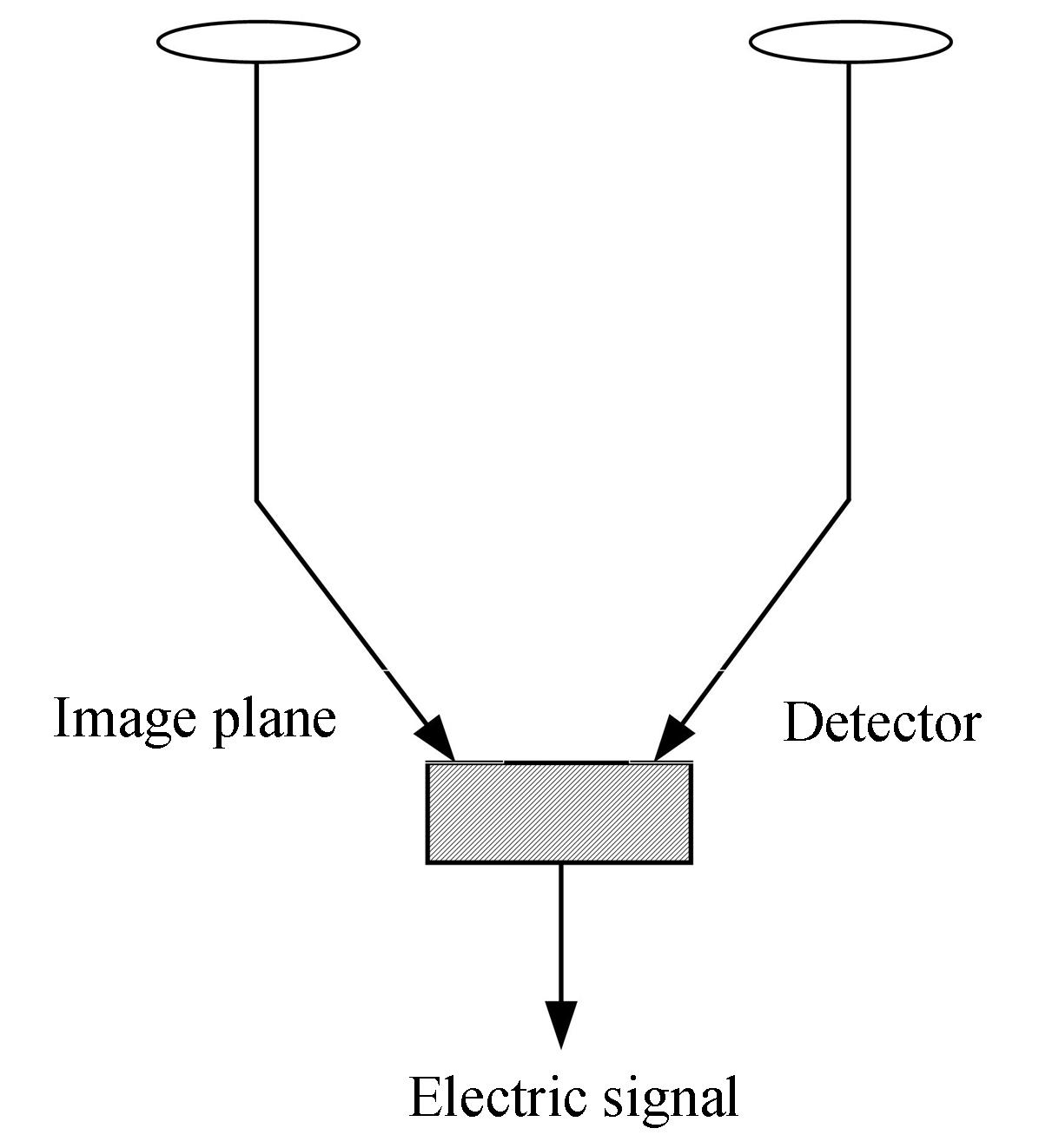
    Fig. 1. The principle of phase array of Fizeau structure
    Laser local oscillator and infrared coherent detection interferometry imaging structure
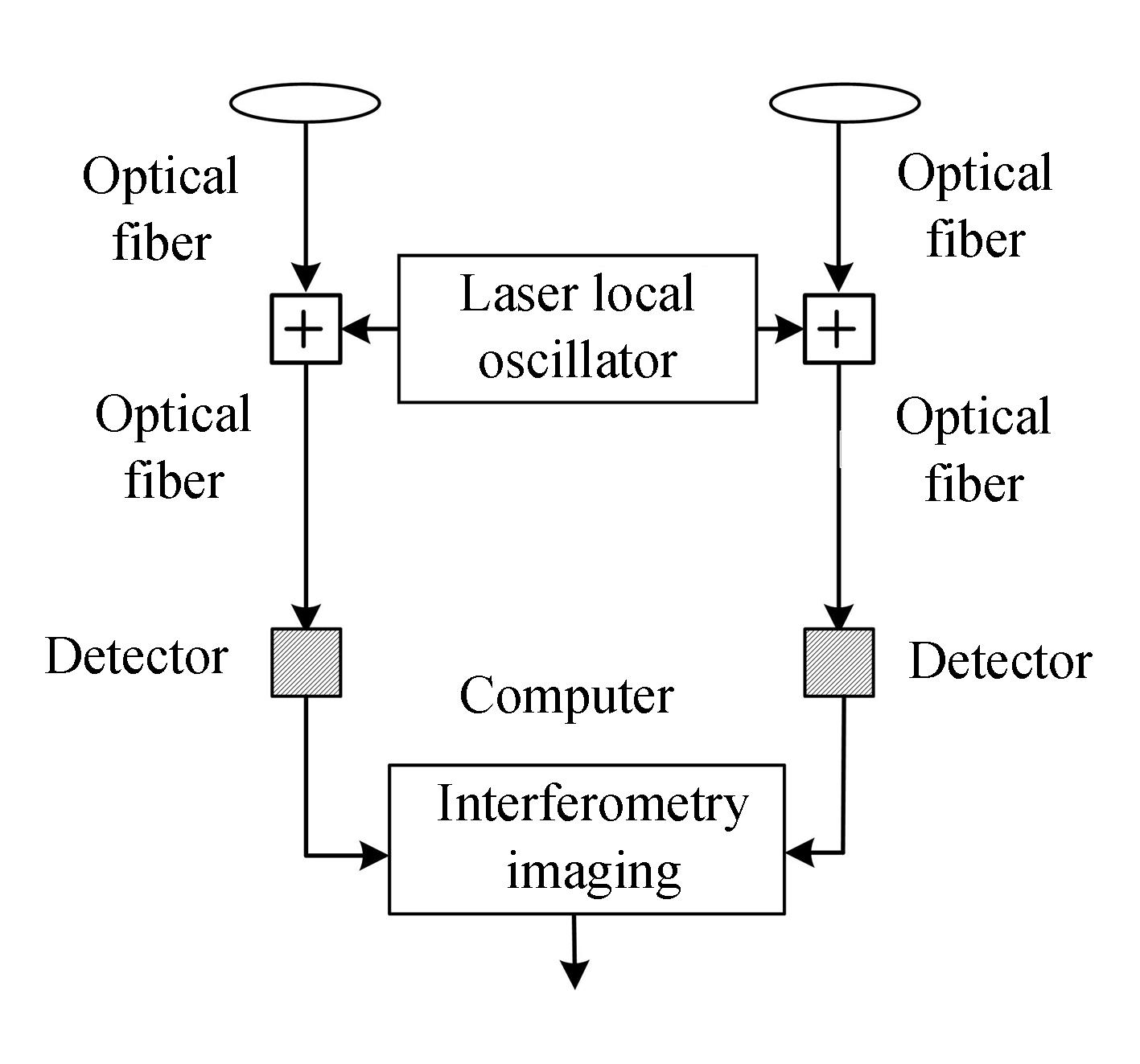
    Fig. 2. Laser local oscillator and infrared coherent detection interferometry imaging structure
    Nano optical waveguide laser local oscillator array detector structure
    Fig. 3. Nano optical waveguide laser local oscillator array detector structure
    The azimuth and elevation direction interferometry phase based on orthogonal baseline and the interferometry imaging results after phase unwrapping
    Fig. 4. The azimuth and elevation direction interferometry phase based on orthogonal baseline and the interferometry imaging results after phase unwrapping
    Schematic diagram of the layout of the infrared interferometry imaging system with 10 m baseline and 2 m aperture suspended in the belly
    Fig. 5. Schematic diagram of the layout of the infrared interferometry imaging system with 10 m baseline and 2 m aperture suspended in the belly
    Schematic diagram of the layout of the infrared interferometry imaging system with 10 m baseline and 2 m aperture suspended on the top of the airship
    Fig. 6. Schematic diagram of the layout of the infrared interferometry imaging system with 10 m baseline and 2 m aperture suspended on the top of the airship
    Infrared imaging optical path diagram based on diffractive optical system
    Fig. 7. Infrared imaging optical path diagram based on diffractive optical system
    Signal processing flowchart of infrared spectrum interferometry imaging
    Fig. 8. Signal processing flowchart of infrared spectrum interferometry imaging
    Comparison of two interferometry fringes with or without autocorrelation
    Fig. 9. Comparison of two interferometry fringes with or without autocorrelation
    Schematic diagram of the optical path of the diffractive optical system
    Fig. 10. Schematic diagram of the optical path of the diffractive optical system
    ParametersValues
    Infrared bandShort wave infrared
    Infrared center wavelength1.55 μm
    Infrared spectral range0.1 μm
    Telescope scanning field of view
    Receiving telescope aperture2 m
    Number of receiving telescopes3 (triangle layout)
    Interferometry baseline length10 m
    Interferometry angle measurement accuracy0.15 μrad
    Equivalent telescope aperture10 m
    Table 1. Main indicators of 10 m baseline 2 m diffraction aperture infrared interferometry imaging system
    Daojing LI, Kai ZHOU, Hao ZHENG, Jinghan GAO, Yanling SUN, Anjing CUI, Jiang WU. Laser Local Oscillator Infrared Spectral Interferometry Imaging and Its Application Prospect for Shipborne Astronomy (Invited)[J]. Acta Photonica Sinica, 2021, 50(2): 1
    Download Citation