
Xiuhua Fu, Ye Wang, Dongmei Liu, Jing Zhang, Gong Zhang, Cheng Lu. Development of Filter Device for Alcohol Vapor Laser Detection System[J]. Chinese Journal of Lasers, 2019, 46(11): 1101003
- Chinese Journal of Lasers
- Vol. 46, Issue 11, 1101003 (2019)
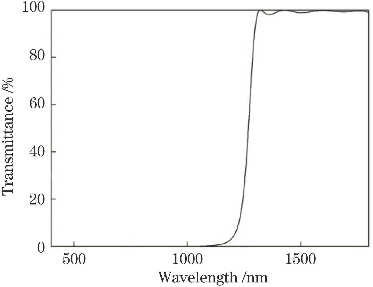
Fig. 1. Definition of the aperture for beam transmission
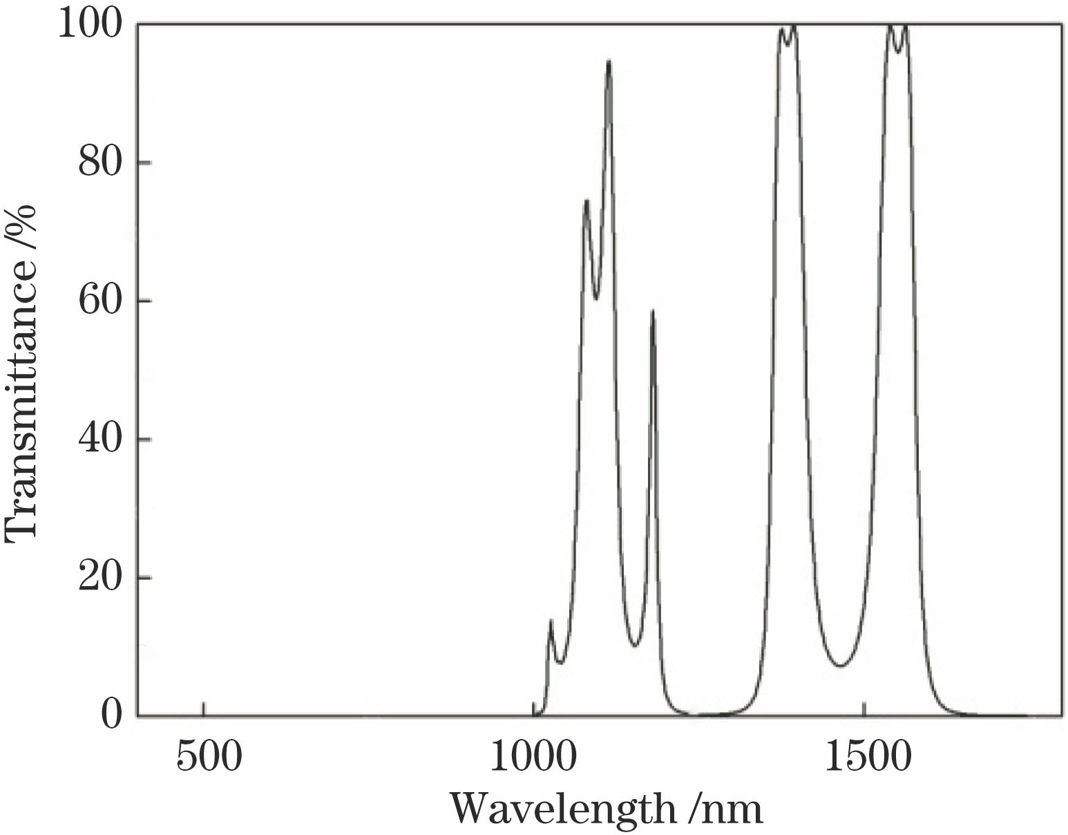
Fig. 2. Transmittance curve of long-wave pass filter film
Fig. 3. Transmittance curve of full-band dual-pass filter film
Fig. 4. Test curve of long-wave pass filter film
Fig. 5. Actual preparation curve of double-sided film layer
Fig. 6. Comparison of spectral red shift before and after secondary baking
Fig. 7. Dual-pass filter film surface peeling at 300 ℃
Fig. 8. Surface of Si substrate before coating
Fig. 9. Test charts of deposition film surfaces at different baking temperatures. (a) 200 ℃; (b) 260 ℃; (c) 300 ℃
Fig. 10. Actual preparation curve of dual-pass filter film
Fig. 11. Spectral fitting of uniform refractive index film
Fig. 12. Diagram of membrane structure
Fig. 13. Fitted curve of gradient index
Fig. 14. Simulation outline of refractive index
Fig. 15. Comparison between spectrum of optimized single-sided filter film and theoretically designed spectrum
Fig. 16. Measured transmittance of double-sided coating filter film
|
Table 1. Design requirements of dual-pass filter

Set citation alerts for the article
Please enter your email address
© Copyright 2018-2021 | Chinese Laser Press. All Rights Reserved 沪ICP备15018463号-20