The use of low-coherence light is expected to be one of the effective ways to suppress or even eliminate the laser–plasma instabilities that arise in attempts to achieve inertial confinement fusion. In this paper, a review of low-coherence high-power laser drivers and related key techniques is first presented. Work at typical low-coherence laser facilities, including Gekko XII, PHEBUS, Pharos III, and Kanal-2 is described. The many key techniques that are used in the research and development of low-coherence laser drivers are described and analyzed, including low-coherence source generation, amplification, harmonic conversion, and beam smoothing of low-coherence light. Then, recent progress achieved by our group in research on a broadband low-coherence laser driver is presented. During the development of our low-coherence high-power laser facility, we have proposed and implemented many key techniques for working with low-coherence light, including source generation, efficient amplification and propagation, harmonic conversion, beam smoothing, and precise beam control. Based on a series of technological breakthroughs, a kilojoule low-coherence laser driver named Kunwu with a coherence time of only 300 fs has been built, and the first round of physical experiments has been completed. This high-power laser facility provides not only a demonstration and verification platform for key techniques and system integration of a low-coherence laser driver, but also a new type of experimental platform for research into, for example, high-energy-density physics and, in particular, laser–plasma interactions.
I. INTRODUCTION
Lasers can concentrate large amounts of energy on very small spatial scales and on extremely short time scales, and are thus among the most effective means to achieve high-energy-density states. Conventional lasers are all characterized by high coherence, narrow linewidth, directionality, and high brightness and have therefore become widely used in fundamental research and in applications in the medical, industrial, military, communications, and other fields. Although traditional high-coherence lasers have provided unprecedented conditions for many areas of scientific research and practical application, the high coherence of the laser can be considered a double-edged sword, since it can lead to unexpected problems arising in certain circumstances. For example, in optical microscopy, environmental scattering causes random phase delays on the particle scale for high-coherence lasers, resulting in interference speckles. This speckle effect will greatly reduce the resolution of the microscope.1,2 For a fiber-optic gyroscope, the long coherence length is likely to increase the amount of noise caused by Fresnel backreflection, Rayleigh backscatter, the nonlinear Kerr effect, and other factors, thereby reducing the accuracy and sensitivity of the gyroscope.3 Similar problems arise in laser-driven inertial confinement fusion (ICF).4 ICF is one of the most promising routes to the generation of clean energy, and there are four leading approaches to its implementation, namely, direct drive, indirect drive, fast ignition, and hybrid drive.5–8 Whichever driving method is used, laser–plasma instability (LPI) is always a critical problem.5,9–11 When laser beams propagate through a plasma, processes such as stimulated Brillouin scattering, stimulated Raman scattering, cross-beam energy transfer, and nonlinear self-focusing occur and have detrimental effects on the fusion process.12,13 These factors have seriously hindered the achievement of controlled fusion in the laboratory.14,15 There are two main reasons why high coherence leads to increased LPI:
High spatial coherence results in a large number of unstable and unpredictable high-intensity regions distributed in the focal spot. The initial wavefront of the laser beam, which is generally obtained by collimating a near-ideal point light source from a single-mode fiber, is nearly an ideal plane wave. However, during stepwise beam expansion, propagation, amplification, harmonic conversion, focusing, etc., the wavefront quality gradually deteriorates owing to factors such as insufficient surface quality of optical components, thermal distortion, and disturbed air. The reduced wavefront quality leads to spatial interference, which in turn causes multiple strong interference speckles in the focal spot. Consequently there are regions in the spot where the local intensity is excessively high, resulting in increased LPI.
High temporal coherence implies a narrow line width and a definite spectral phase relationship. These result in two effects: first, the conditions for the occurrence and growth of parametric instability can be easily satisfied; second, the strong speckle distribution in the focal spot remains stable, and LPI occurs and increases with time.
Since the 1980s, many efforts have been made to overcome these problems. In general, two approaches have been adopted.
The first approach retains the original high-coherence laser drivers and relies on improved beam control (beam smoothing techniques) to reduce the negative impact of coherence. This has been the main direction of laser driver development in recent decades. The smoothing techniques involve two steps. In the first step, two-dimensional near-field phase elements [such as distributed phase plates (DPPs), continuous phase plates (CPPs), and lens array (LAs)] are used to expand the far-field focal spot size of the beam.16–19 The middle- and low-frequency components of the focal spot intensity distribution are spatially shaped to obtain a uniform profile, reducing the probability of ultrahigh power densities occurring and thereby reducing the degree of LPI. In the second step, the smoothing by spectral dispersion (SSD) technique20 is used to broaden the spectral width of the original beam through phase modulation. Then, in combination with a grating, a time-varying angular sweep of the beam speckles (corresponding to a spatial sweep of the speckle positions) in the focal area is introduced to perform temporal smoothing. The broadening of the spectrum and the spatial variation of the speckle distribution with time in this step are expected to have a positive effect on the suppression of LPI.21
The second approach is to develop a brand new low-coherence laser driver to directly obtain a low-coherence driven source with lower temporal and spatial coherence and better smoothing. In general, there are two ways to obtain a low-coherence driven source. One way uses a pulse source with low temporal and high spatial coherence so that, after propagation, amplification, and harmonic conversion, a high-energy laser pulse with low temporal and high spatial coherence is produced. A beam smoothing technique [e.g., induced spatial incoherence (ISI)22] is then applied to give a driving field with low temporal and low spatial coherence. The other way is to use a pulse source with low temporal and low spatial coherence directly. After propagation, amplification, and harmonic conversion, a high-energy driving pulse with low temporal and low spatial coherence is obtained.23
The use of traditional high-coherence laser drivers together with beam smoothing techniques has always been the mainstream approach to reducing LPI in ICF. Facilities based on this approach, represented by Nova, OMEGA, the National Ignition Facility (NIF), Laser Mégajoule, GEKKO, and the Shenguang series, have made great contributions to ICF research.12,24–29 Moreover, a large number of experimental and theoretical studies have shown that the decoherence techniques used in current laser drivers, such as CPPs,18 SSD,20 and polarization smoothing (PS),30 can suppress the detrimental effects of LPI under certain conditions. However, some researchers in the field of ICF believe that low-coherence drivers, which have greater output bandwidth and lower temporal and spatial coherence, may have a better smoothing effect and greater potential to suppress or even completely overcome LPI, and they have therefore suggested that using low-coherence light with broad bandwidth is a viable alternative approach.5,12,31–33 In the 1990s, many laboratories explored the use of low-coherence light in a series of facilities, including Pharos III, Gekko XII, PHEBUS, and Kanal-2.23,34–36 However, the progress of these investigations was hampered by the level of development of laser technology at the time, and they encountered many bottlenecks and difficulties related, for example, to the generation of low-coherence sources, the efficient amplification and safe propagation of low-coherence pulses, and the efficient harmonic conversion of low-coherence pulses. In the subsequent decades, it generally came to be accepted that ignition would be realized based on traditional high-coherence lasers combined with beam smoothing techniques (CPP + SSD + polarization smoothing).37,38 In addition, there was a lack of significant progress both in the key technology of low-coherence drivers and in studies of the interaction between low-coherence light and matter.39 Thus, research into low-coherence laser driver technology basically stagnated. However, with the activation of the NIF, and especially with the completion of the National Ignition Campaign, it became clear that the suppressive effects of existing decoherence methods based on beam smoothing of high-coherence lasers are limited and that this approach is unable to overcome LPI completely. There is a need for further substantial reductions in the temporal and spatial coherence of driving pulses. In this context, efforts have resumed to explore the feasibility of low-coherence laser drivers.40–42
To overcome the technical bottlenecks that have limited the development of low-coherence drivers, such as those related to generation and control of low-coherence sources, broadband amplification, high-efficiency harmonic conversion, and beam smoothing of low-coherence pulses, our team has carried out a series of key studies since 2016.43–50 The superluminescent diode (SLD) has been introduced into the ICF field for the first time as a lower-coherence seed source. When this is combined with precise temporal shaping and spectral control techniques, the temporal and spectral profiles of a low-coherence pulse can be precisely shaped. In the amplification sections, multilevel spectral shaping filters have been adopted to suppress the spectral narrowing of the laser system. Under high-gain conditions (>107 times), with Nd:glass rod amplifiers, a low-temporal-coherence pulse with tens of joules of energy and a large bandwidth (15 nm) has been created. The corresponding coherence time is only 270 fs. With Nd:glass disk amplifiers, a kilojoule-level, several-nanosecond pulse with a bandwidth of 13 nm and a coherence time of 290 fs has been produced without damage. A new approach to harmonic conversion of low-temporal-coherence pulses has allowed low-coherence second-harmonic generation (SHG) with an efficiency of up to 70% and a bandwidth of 3 nm with the use of a potassium dideuterium phosphate (DKDP) crystal. A 520 J pulse with a coherence time of 300 fs has been produced by using a large-aperture potassium dihydrogen phosphate (KDP) crystal. A beam smoothing technique combining a LA or a CPP with the ISI method gives a focal spot with good uniformity and a fast smoothing time. The low-coherence laser facility, named Kunwu, provides a new type of experimental platform for a variety of studies, including those of laser–plasma interaction and high-energy-density physics.
The structure of the remainder of this paper is as follows. Section II gives an overview of the historical development of low-coherence high-power laser drivers. The subsequent sections describe the techniques developed in our institute for generation and control (Sec. III), broadband amplification (Sec. IV), efficient frequency conversion (Sec. V), and temporal and spatial beam smoothing (Sec. VI) of low-coherence pulses. Finally, Sec. VII is devoted to our conclusions.
II. HISTORICAL DEVELOPMENT OF LOW-COHERENCE HIGH-POWER LASER DRIVERS
To aid the development of ICF based on low-coherence laser drivers, the key techniques involved and the ways in which they are integrated have been investigated in many high-power laser laboratories around the world. The most representative of these facilities are Gekko XII, PHEBUS, Pharos III, and Kanal-2. In this section, we will use the results of the work done in these facilities to analyze key aspects of low-coherence drivers, including source generation, amplification, harmonic conversion, and beam smoothing of low-coherence pulses.
A. Low-coherence light source
In a high-power laser facility, the system starts with the front-end laser source. Its main function is to provide different kinds of seed sources for the laser system as a whole and to control various properties of the laser pulse, such as the temporal pulse shape, the spectral characteristics, and the spatial intensity distribution.51–53 In the last two decades, research on low-coherence front-end sources has been carried out in a number of countries, including Japan, the USA, France, and Russia. In the following subsections, different front-end techniques are analyzed and compared.
1. Partially coherent (both temporal and spatial) light source based on amplified spontaneous emission
In the 1990s, Nakano and co-workers reported the characteristics of a partially coherent light source for the high-power Nd-phosphate glass laser system Gekko XII at the Institute of Laser Engineering, Osaka University.35,54,55 The amplified spontaneous emission (ASE) front-end system consisted of an ASE generator, a four-pass rod amplifier, a spectral disperser, and a pulse shaper. A flash-pumped Nd:glass rod with a diameter of 25 mm and a gain length of 300 mm (Hoya LHG-8, 2 wt. % Nd2O3) was used to produce ASE light. The structure of the ASE generator was similar to a concave–convex cavity, which gives increased temporal and spatial coherence. After the four-pass rod amplifier, the pulses were amplified to 10 µJ/ns with a nominal gain of 107. As a result of the finite spectral response of the four-pass rod amplifier, the spectral width was narrowed to less than 2 nm. A pulse selector consisting of three Pockels cells with 12 polarizers was used to shape the pulse width. Owing to the rise time of the driver, the shortest pulse duration obtained was limited to 1 ns. Anyway, owing to the constraint imposed by the spatial and temporal modes, this type of source based on ASE still has relatively high temporal and spatial coherence and thus is not the ideal low-coherence light.
2. Low-spatial-coherence laser source based on a mode-locked oscillator
Another method for generating partially coherent light on Gekko XII used a mode-locked oscillator and multimode optical fibers.56 Instead of the ASE broadband oscillator described above, the oscillator here was an actively mode-locked Nd-doped yttrium lithium fluoride (Nd:YLF) oscillator, which generated a train of transform-limited 120-ps pulses at a central wavelength of 1053 nm. Obviously, this was a high-temporal-coherence laser oscillator. The spectral width was adjusted to about 0.6 nm. A grating pair then compressed the chirped pulse to 15 ps, which is approximately equal to the coherence time. A pulse sequence with a separation of 100 ps was produced through a 32-channel fiber divider and coupler. The output pulse train was incident into a step-index multimode fiber to reduce the spatial coherence. The core size, length, and numerical aperture of the multimode fiber were 200 µm, 200 m, and 0.2, respectively. The beam divergence of the mode dispersed beam was about 66 times diffraction-limited. In other words, the light source had very high temporal coherence and relatively high spatial coherence, even with the use of a multimode fiber to induce spatial incoherence.
3. Q-switched low-coherence laser sources
B. Amplification
Whether the laser source is ASE or some other broadband oscillator, it needs to be amplified to achieve the high energies required for applications. In the low-coherence large-scale laser facilities discussed here, the typical amplification process was to inject the low-coherence front-end source with temporal and spatial shaping into a Nd:glass amplification chain. High-energy output pulses were obtained by means of the gain of the Nd:glass system.
1. Amplification of partially coherent (both temporal and spatial) sources based on ASE
The amplification and propagation of partially coherent ASE from a high-power Nd:glass system was first demonstrated on the Gekko XII laser facility. The amplification chains of Gekko XII are divided into a preamplifier and a main amplifier.28 The preamplifier consists of four rod amplifiers each with a diameter of 25 mm. The main amplifier includes two 50-mm-diameter rod amplifiers and five disk amplifiers, and the beam size at its output is 320 mm.
After the injected ASE (about 0.5 µJ, 1.6 nm, 3 ns) was amplified by the amplification chain, the energy reached 800 J and the spectral width was typically 1.3 nm (the corresponding flux of the main amplifier output was 1 J/cm2 and the power density was 0.3 GW/cm2).54 No remarkable gain reduction or spectral narrowing were found during the amplification process with the incident spectral width in the range of 0.1 nm–2.0 nm. To better understand the gain characteristics and spectral changes of the ASE pulse, numerical simulations were performed based on an extension of the Frantz–Nodvik equation.61 The results were in good agreement with the experimental measurements.
It is well known that amplification and propagation of high-coherence light always induces hot-spot structures in the far-field region owing to the phase-front distortion in the near-field. However, this is not the case for partially coherent light, because the nonuniform irradiation distribution causes an interference effect that undergoes rapid temporal changes owing to the short coherence time compared with the pulse duration. Compared with traditional lasers, the uniform output radiation in the quasi-far-field region is predictable for ASE. It is worth noting that the temporal profile of the amplified ASE has complex fine intensity spikes with a duration of about the reciprocal of the frequency width, and the spatial profile as measured by a streak camera is random, as shown in Fig. 3 in Ref. 54. The instantaneous speckles of the ASE may cause nonlinear index effects in the glass, risking damage to the amplifying element and severely limiting the output capability of the system. The main reason for this is that the partially coherent source employed (an ASE source generated by the method described in Sec. II A 1) has relatively high temporal and spatial coherence.
2. Amplification of low-spatial-coherence laser source based on a mode-locked oscillator
When pulses from the actively mode-locked Nd:YLF oscillator described in Sec. II A 2 were injected into the Gekko XII amplification system, an output beam of energy 120 J and diameter of 320 mm was obtained.56 Few reports of results with this setup are available. However, according to our understanding, both the temporal and spatial coherence of these pulses are the highest among all of the sources mentioned above, so the temporal and spatial characteristics of the pulses after amplification and propagation should be the poorest. The corresponding safe output capability of the facility would thus be the lowest, and therefore a facility with this source will be of no practical value. A comparison of the output energies reported above confirms this.
3. Amplification of Q-switched low-coherence laser sources
C. Frequency conversion
Second-harmonic generation (SHG) was first demonstrated by Franken et al.67 at the University of Michigan, Ann Arbor, in 1961. This demonstration was only possible because of the invention of the laser, which produced the required high-intensity coherent light. A theoretical foundation for SHG was initially presented in 1962 by Bloembergen and Pershan,68 who obtained solutions of Maxwell’s equations at the planar interface between a linear and a nonlinear medium, taking account of the conditions of energy and momentum conservation.
Taking type I phase matching in a KDP crystal as an example, an extraordinary frequency-doubled photon is generated by two ordinary light photons, both of which are fundamental waves. The phase-matching condition can be written asIn Ref. 68, two parameters are introduced to describe the requirements for efficient SHG:where C is a quality parameter characterizing the nonlinear effect of the crystal, I is the intensity of the fundamental frequency, l is the crystal length, and Δk(ω, θ) = 4π[n(2ω, θ) − n(ω)]/λ. In general, η is about 4–5, δ ≪ π/10, and Δk is a function of frequency and angle in the crystal at room temperature, which can be expanded in a Taylor series at the phase-matching angle:In general, any wave-front distortion or spectral broadening will decrease the efficiency of frequency doubling. Efficient harmonic conversion of low-coherence pulses is a major technical obstacle that hinders the development of low-coherence high-power laser facilities.
Previous research on the harmonic conversion of low-temporal-coherence pulses has mainly focused on the problem of how to achieve group-velocity matching under large-bandwidth conditions. For broadband lasers, the overall group-velocity mismatch between the fundamental wave and the second-harmonic wave in the crystal needs to be sufficiently small compared with the fundamental pulse coherence time.34,69 Several methods have been implemented to compensate for group-velocity mismatching, and these can be divided into two categories. The first category of methods are based on the use of special geometries and include achromatic phase matching,34,69,70 multicrystal sequences,71 tilted quasi-phase-matched gratings,72 and Čerenkov phase matching.73 These methods are difficult to implement given the restrictions imposed by the need for beam alignment, and the efficiency of frequency doubling when they are used is lower than that predicted theoretically. The second category use so-called spectrally noncritical phase matching,74–79 which takes advantage of the fact that there exists a zero-group-velocity mismatching wavelength of SHG for a specific crystal, the conditions for which can be written asIn this case, the doubling configuration is just like the conventional one, and no modification of the input light is needed, which makes this approach more practical in terms of simplicity, reliability, and conversion efficiency. Fortunately, partially deuterated KDP was found to be suitable for broadband SHG in the region from 1.034 μm to 1.179 μm.79 This is very important for the Nd:glass lasers that are used to study ICF. Some of the approaches mentioned above have been adopted in Nd:glass facilities. Schemes such as time walk-off compensation, angular dispersion compensation, and chirp modulation matching are reviewed below.
1. Group-velocity mismatch compensation with multicrystals
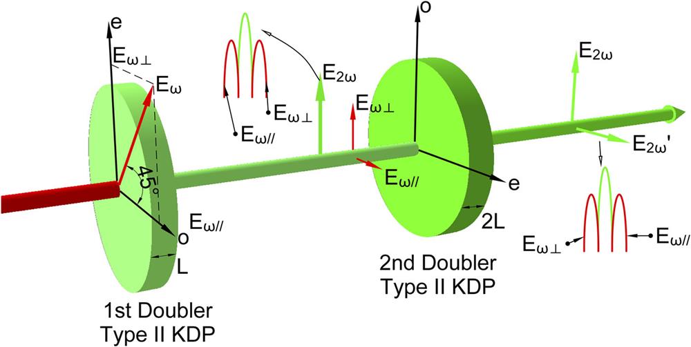
Pronko et al.34 used two type II KDP crystals in a quadrature arrangement for frequency doubling of broadband high-peak-power Nd:glass laser radiation. The quadrature configuration compensates for group-velocity mismatching because the transverse projections of the principal axes of the two crystals are orthogonal, as shown in Fig. 1. Hence, the fundamental component, which is polarized along the slow axis in the first crystal, will be polarized along the fast axis in the second. If the thickness of the second crystal is twice that of the first, the walk-off will be compensated, and the second harmonic will be generated efficiently along most of its path. This method has been verified on the Pharos III laser. The bandwidth of the fundamental wave is about 2 nm, which is composed of multilongitudinal modes. The conversion efficiency can reach 55% at a pumped intensity of ∼1 GW/cm2. The main disadvantage of this method is that the output second-harmonic pulses have random polarization. Also, the conversion efficiency will decrease with larger bandwidth. In Ref. 80, it was reported that the first and second crystal were detuned in opposite directions to correspond to different matching wavelengths, and the acceptance bandwidth could be up to 10 nm with optimization. Experimentally, the conversion is found to be nearly 60% for a chirped pulse of bandwidth about 3.2 nm. However, the frequency-doubled light suffers temporal distortion during the depolarization.
Figure 1.SHG with two type II crystals in quadrature.
Eimerl et al.81 proposed a broadband frequency-tripling method using a crystal cascade as shown in Fig. 2. This method has been demonstrated experimentally for radiation of 1 nm bandwidth on the OMEGA facility82 at the University of Rochester.83 The principle is similar to quasi-phase matching: when the phase difference L Δ k of the three waves in the crystal reaches a value of π, “back-conversion” will occur, that is, the light generated will return to the fundamental wave and the second harmonic. Dispersion by the air in the gap between the two crystals can be utilized to suppress this back-conversion. Theoretically, the conversion efficiency can exceed 70% for 300-GHz bandwidth (1053 nm), but the three-wave phase difference is related not only to the detuning angle, but also to the pump intensity.
Figure 2.Broadband frequency tripling with two triplers for the OMEGA facility.
2. Group-velocity mismatch compensation with grating angular dispersion
Spontaneous radiation or chirped pulses were used as the seed in the Gekko XII facility, with a bandwidth of about 1 nm.35 The angular dispersion dθ/dλ of spectral dispersion smoothing was about 239 µrad/nm, which is equal to the wavelength-dependent phase-matching angle near 1053 nm in KDP for type II frequency doubling. This was used to compensate for the phase mismatching caused by the broader bandwidth, and the frequency-doubling conversion efficiency was about 50% with a pumping intensity of ∼0.3 GW/cm2. In fact, group-velocity mismatching is not obvious at 1053 nm for type I SHG, as long as the pump light intensity is increased. The crystal thickness can be appropriately reduced to obtain high efficiency for 1 nm–2 nm bandwidth.
A similar design was applied in the PHEBUS facility.59 The seed from the multimode oscillator was amplified by the Nd:glass system, and a spatial chirp was then introduced through a grating pair, such that different positions on the beam cross section corresponded to different frequencies.59 A cylindrical lens placed downstream provided angular dispersion. If the change of the crystal matching angle with frequency was consistent with this angular dispersion, a relatively efficient broadband frequency doubling could be achieved. It was reported that the frequency-doubling conversion efficiency was ∼30% for a beam with a bandwidth of 3 nm. This low conversion efficiency could have been caused by the complicated beam alignment and poor beam quality.
3. Group-velocity mismatch compensation with phase modulation
Migus84,85 and Qian86 both proposed a broadband frequency-doubling and -tripling method based on pulse chirp modulation. As illustrated in Fig. 3 (see Ref. 84), the phase mismatch is a function of time for a chirp pulse. If the chirp parameter is chosen to make Δk = 0, then the conversion efficiency can be significantly increased. This approach was demonstrated experimentally by Raoult et al.84 The bandwidth of the triple frequency was about 1.2 nm, and the pulse could be compressed to 220 fs. However, this method has not yet been applied at any high-power laser facility, possibly because of its complexity.
Figure 3.Phase-matching curve for frequency tripling of chirp pulses. Reprinted with permission from Raoult et al., Opt. Lett. 24(5), 354-356 (1999). Copyright 1999 Optical Society of America.
Chen et al.87 demonstrated that the tripling scheme can support a bandwidth as large as 5 nm if the effects of group-velocity mismatching are ameliorated through frequency mixing of a broadband chirped pulse with a narrowband laser pulse.
4. Wavelength-insensitive phase-matched SHG in partially deuterated KDP
The aforementioned schemes are too complicated to implement in large laser facilities. Adopting a different approach, Webb et al.79 experimentally determined the spectrally noncritical phase-matching behavior of type I SHG in KDP and its dependence on the deuteration level in partially deuterated KD*P. The first-order wavelength–sensitivity parameter ∂k/∂ω for type I SHG of 1.053 µm light vanishes for a KD*P crystal with a deuteration level of 12% ± 2%. Using this configuration, Zhu et al.88 experimentally and numerically investigated the characteristics of SHG with a femtosecond laser at 1 µm. They found that it was possible to support efficient SHG over 20 nm bandwidth of the fundamental wave at 1 µm in a 10-mm-long crystal. As suggested in Ref. 79, this method can be utilized for large-aperture beams, and KDP analogs are the only suitable crystals.
Many other concepts have been proposed for broadband frequency doubling or tripling. By applying a longitudinal gradient temperature field to a lithium triborate (LBO) crystal, Rozenberg and Arie89 were able to achieve an acceptance bandwidth of SHG reaching ∼10 nm. Yuan et al.90 proposed that the acceptance bandwidth of frequency tripling could be improved by using a segmented partially deuterated KDP crystal with discrete values of deuteration.
As is well known, the intensity fluctuation period of a low-temporal-coherence pulse is close to the coherence time. When the pulse duration is far greater than the coherence time, fluctuations of the phase difference between the fundamental wave and the second harmonic caused by the walk-off effect impose the main restriction on the efficiency of SHG. All of the methods described above can reduce these fluctuations and effectively improve the conversion efficiency. However, the methods in the second category are better suited to engineering applications.
As well as group-velocity mismatching, the physical processes involved in harmonic conversion of low-temporal-coherence pulses need to be better understood. The progress that we have achieved so far in this area will be described in subsequent sections. As far as achieving harmonic conversion of low-spatial-coherence pulses is concerned, this mainly requires matching of spatial wave vectors. Low-spatial-coherence pulses are not essential for low-coherence drivers: for instance, in the amplification and harmonic conversion sections, we can use beams with high spatial but low temporal coherence and then induce spatial incoherence during the focusing stage to reduce the spatial coherence of the focused beam. Therefore, we shall not discuss these further in this paper.
D. Beam smoothing in low-coherence high-power laser drivers
In a low-coherence high-power laser system, focal spot conditioning is a key factor affecting energy transfer from the laser to the target. In ICF experiments and equation-of-states determinations, the focal spot needs to be uniform to avoid hydrodynamic instability and LPI. In these experiments, the root mean square (rms) of the focal spot intensity distribution should be a few percent or even less,91 and this should be achieved within a few hundred picoseconds or even shorter. However, owing to thermal distortion of the amplifying medium, nonideal optics, air disturbances, and so on, the wave front of the output pulse in a real high-power laser system is severely and randomly distorted, and its focal spot distribution is uneven and unstable. To achieve focal spot conditioning in a low-coherence laser system, many beam smoothing methods have been proposed. These methods can be divided into three categories: spatial smoothing methods that can tailor the overall shape of the focal spot, temporal smoothing methods that eliminate speckling by rapidly changing the focal spot details over time, and far-field image transfer methods that have both temporal and spatial smoothing effects.
1. Spatial smoothing methods
Most spatial smoothing methods rely on modulation of the wave front distribution in the near field, as shown in Fig. 4. According to Fresnel diffraction theory, the near field and far field of the light are Fourier transforms of each other. Therefore, the far-field distribution can be modified by modulating the phase of the near field. For low-spatial-coherence light, Fresnel’s diffraction law should be used with ensemble theory or statistical optics to predict the effect of phase modulation. The methods using continuous phase plates (CPPs) and lens arrays (LAs) belong to this type.
Figure 4.Focal spot reshaping using a phase element.
Random phase plates (RPPs) were proposed in 1984 by Kato et al.17,92 An RPP consists of small blocks of different thicknesses. The phase differences introduced by these small blocks are randomly distributed between 0 and π. The focal spot formed by an RPP is similar to a Gaussian function with speckles. However, sometimes it is more desirable to obtain a flat focal spot with a super-Gaussian distribution, which is one of the disadvantages of RPPs. At the same time, discontinuities in an RPP will cause energy loss due to diffraction. Distributed phase plates (DPPs) were proposed to avoid the energy loss in RPPs, but it is still difficult to design the intensity distribution of the focal spot.93 Kinoform phase plates were designed for better control of focal spot distribution, but they still suffer from the problem of energy loss.94 To overcome these shortcomings, CPPs were proposed.16 Since discontinuities in the phase plate distribution are then avoided, the diffraction efficiency of a CPP can theoretically reach 100%. With appropriate use of a frequency filter and phase unwrapping methods together with the conventional Gerchberg–Saxton method, a CPP can be designed to obtain a far-field distribution with a certain envelope.95
The use of LAs was proposed in 1986 by Deng et al.19 In this method, in addition to the main lens, an additional array of lenses is added to obtain quasi-near-field illumination. Ideally, the focal spot of this LA will be the quasi-near field of a single small beam multiplied by the Dirichlet kernel. The diffraction effect of small beams will cause low-spatial-frequency intensity fluctuations, and the Dirichlet kernel will cause high-frequency intensity modulation in the focal spot.
The use of CPPs and LAs is not sensitive to wave-front distortion, because the wave-front modulation introduced by these methods has a higher spatial frequency than the distortion. Therefore, these schemes can be applied to high-power lasers to obtain a relatively stable and flat focal spot. Although those spatial smoothing methods are effective for tailoring the envelope of the focal spot, speckles still exist in the spot. These speckles come from interference of the near field. The size of the speckles is close to the diffraction limit of the beam. Temporal smoothing methods need to be used for the suppression of speckles.
2. Temporal smoothing methods
The way to eliminate speckling is to use a temporal smoothing scheme that can smooth the speckles in the far field after a sufficient smoothing time by changing the far field rapidly with time. Temporal smoothing methods for low-coherence lasers mainly include induced spatial incoherence (ISI), angular dispersion of the spectrum, and polarization smoothing. The key factor in temporal smoothing is decorrelation of the near field or the introduction of low spatial incoherence.
ISI was proposed in 1983 by Lehmberg and Obenschain.22,96 Time delays greater than the coherence time of light are added to different areas of the laser in the near field. In the early ISI experimental design,97 the delay effect was introduced by using a pair of relatively thick stepped mirrors. On a laser with sufficient bandwidth, a stair-shaped plate can be used to achieve such an effect, as shown in Fig. 5. The whole beam will be divided into small beamlets with different time delays, and these beamlets are incoherent with each other. The incoherent beamlets will be superimposed on the focal plane to eliminate speckles caused by interference. The instantaneous intensity distribution of the focal spot is still speckled and highly uneven. However, this distribution changes rapidly with time, and, after sufficient integration time, a smoothed focal spot intensity distribution without speckles can be obtained.
Figure 5.Schematic of the ISI method. Reprinted with permission from Zhao et al., Appl. Opt. 58(8), 2121–2126 (2019). Copyright 2019 Optical Society of America.
Angular dispersion of the spectrum was proposed in 1993 by Nakano et al.55 This method is very similar to the smoothing by spectral dispersion (SSD) method,20,98–101 but the latter is generally used on narrow-bandwidth laser systems.102 When used in a broadband low-coherence laser system, the SSD method cannot take advantage of the broadband characteristics of the laser. In angular dispersion of the spectrum, different spectral components of the light are dispersed in different directions. On the focal plane, light fields with different frequencies have different displacements owing to dispersion, and the total focal spot uniformity is improved because of the intensity superposition. In one-dimensional angular dispersion of the spectrum, the speckles in the direction of dispersion are smoothed, while those in the vertical direction are not completely removed. Two-dimensional dispersion smooths speckles in all directions.
Polarization smoothing is another temporal smoothing method. Its original form was the polarization control plate, which was proposed by Gunderman et al.103 and Tsubakimoto et al.104 However, a simpler device can be used for polarization smoothing. If birefringent material is used,30,105 the beam is divided into two perpendicular polarized beams with slightly different angles, and their focal spots are added by intensity to obtain an instantaneous smoothing effect. Although it is mainly used on conventional narrow-bandwidth laser systems, polarization smoothing can also be applied to low-coherence laser systems.
When the above methods are adopted, temporal smoothing is realized by artificially reducing the spatial coherence of the beam. There is some freedom in the placement of these additional optical components in the optical chain. For example, we can place the ISI plate in front of the final focusing lens or with the spatial filter in front of the main amplifier. However, in the second case, the effect of low spatial coherence on the propagation, amplification, and frequency conversion of the beam needs to be estimated.
3. Far-field transfer method
Smoothing methods based on far-field image transfer are mainly used on low-spatial-coherence sources, where they have both temporal and spatial smoothing effects. Echelon-free ISI22,106 on the Nike laser and partially coherent light smoothing on PHEBUS belong to this type of beam smoothing method. In these methods, the far-field shape (i.e., the divergence angle) of the beam is directly adjusted by the mode-limiting hole (or the end face of the multimode fiber) before the amplification stage. After amplification, the far field of the beam reaches the target through image transfer. In this way, the number of spatial modes determines the smoothed spatial distribution. Speckles can be eliminated by using large numbers of spatial modes. In these methods, image transfer is able to control the focal spot shape because low-spatial-coherence light has large divergence angles, and so distortion in the optical path has little effect on the far-field shape.
The echelon-free ISI method is an improved version of traditional ISI and can be employed on low-spatial-coherence lasers, such as KrF lasers. Figure 6(a) shows the echelon-free ISI on the Nike KrF laser. By using a broadband ASE oscillator source, and based on the principle of image transfer, the shape of the focal spot can be changed directly by controlling the variable-density absorber at the front. In the PHEBUS facility based on a Nd:glass laser, the beam smoothing method used is called partially coherent light smoothing.107 This method utilizes the spatial mode dispersion of a multimode fiber to obtain low-spatial-coherence light, as demonstrated in Fig. 6(b). With proper design of the image transfer system of the beam, the focal spot is expected to be an image of the multimode fiber output surface. Both methods utilize image transfer of a low-spatial-coherence laser to obtain the desired focal spot shape. Instantaneously, the focal spot still has a distribution of speckles. However, with image transfer, the statistical characteristics of the low-spatial-coherence light ensure that the focal spot distribution tends to become flat after sufficient smoothing time. Far-field transfer methods can obtain a focal spot with excellent uniformity (i.e., rms < 1%), as reported for the Nike facility.105 The disadvantage is that the propagation of a low-spatial-coherence laser with large emission angle increases the complexity of the laser system.
Figure 6.(a) Demonstration of the echelon-free ISI method. Reprinted with permission from Lehmberg et al., J. Appl. Phys. 62(7), 2680–2701 (1987). Copyright 1987 AIP Publishing LLC. (b) Spatial mode dispersion in the optical fiber smoothing method. Reprinted with permission from Veron et al., Opt. Commun. 65, 42–46 (1988). Copyright 1988 Elsevier.
As mentioned above, many efforts have been made to obtain low-coherence high-power light pulses. However, owing to the limitations imposed by the source generation technology, amplification and propagation, beam quality control, and efficient harmonic conversion of low-coherence light pulses, the development of this field has faced great challenges. Several years ago, a brand-new scheme for achieving a low-coherence high-power laser driver was proposed in our institute. After several years of work, a kilojoule low-coherence laser driving facility has been successfully developed and has recently been put into service for experimental physics research. In the following sections, the progress made by our research team in key techniques, related theories, and verification of system integration will be described in detail.
III. GENERATION AND CONTROL OF INSTANTANEOUS BROADBAND LOW-COHERENCE PULSES
It is generally believed that broadband laser drivers have two main advantages compared with traditional high-coherence laser drivers (including various beam smoothing techniques): (1) larger output bandwidth—by increasing the bandwidth, it is possible to suppress the growth of parametric instability during laser–plasma interaction; (2) better smoothing of the focal spot—the larger the bandwidth and the more abundant the spectral components, the better is the integral smoothing effect. However, in recent years, there has been growing realization that relying on these two advantages alone is not enough to overcome the problems encountered in attempting to achieve ignition. For example, some efforts have been made to use broadband chirped pulses to suppress LPI, but the effects have been limited according to both theoretical simulations and experimental studies.108
In recent years, LPI studies have shown that the growth time of parametric saturation is of the order of picoseconds. For low-coherence light, if the spectral characteristics of the speckles and the time evolution characteristics of their spatial or longitudinal intensity distribution exhibit significant differences compared with those of traditional lasers on a picosecond time scale or the corresponding spatial length scale, then it could be possible to exploit these differences to suppress the effect of LPI. In addition to the broadband characteristic, two additional features need to be added to a broadband source to meet the above requirements: (1) instantaneous broadband characteristics, i.e., the spectral bandwidth on any sub-picosecond time scale should be equivalent to the integral spectral bandwidth of the entire pulse; (2) spectral incoherence, i.e., there should be no correlated and definite phase relationship among the spectral components. If a low-coherence beam with these characteristics is subjected to spatial smoothing, then, on the one hand, the broad spectral characteristics of an instantaneous broadband pulse are expected to delay the growth time of LPI, and, on the other hand, the sub-picosecond rapidly changing 3D distributed speckle field is expected to effectively cut off the path of LPI growth in the high-intensity region of the speckles. The combination of the above two requirements is expected not only to alleviate or even eliminate the problem of LPI, but also to greatly improve the smoothness of the focal spot.42,109
Figure 7 shows the beam characteristics that the brand new low-coherence pulse should have. Owing to the features of high coherence and narrow linewidth, the time–frequency diagram of traditional lasers is a single time-invariant spectral line, as shown in Fig. 7(a1). For a certain instant, the spectrum and phase are fixed and single, and there is a single isolated point on the frequency–phase diagram, as shown in Fig. 7(a2). The chirped pulse introduces second-order dispersion to broadband phase-locked light, i.e., the spectral components are linearly stretched in time. On the time–frequency diagram, there is a straight line whose frequency changes linearly with time [Fig. 7(b1)]. However, on a given instantaneous frequency–phase diagram, there is still a single point composed of a single spectrum and a single phase [Fig. 7(b2)]. In contrast to Fig. 7(a1), where the spectrum does not change, the frequency and phase of the chirped pulse change with time, and thus the positions are different. Different spectra of the transform-limited pulse propagate simultaneously because there is no residual dispersion. Therefore, at a given time, all frequencies of the transform-limited pulse have the same phase, i.e., there is a flat line on the frequency–phase diagram, as shown in Figs. 7(b1) and 7(b2). The time–frequency characteristic of a phase-modulated pulse obtained by the SSD technique is shown in Fig. 7(c1). The SSD technique sweeps the spectrum of the phase-modulated pulse periodically, and so isolated frequencies have different phases at a given time, as shown in Fig. 7(c2). Unlike the above-mentioned pulses, the frequencies of an instantaneous broadband pulse are broadband and plentiful at any instant of time, similar to the effect of “white light,” as shown in Fig. 7(d1). Moreover, different spectra have no fixed phase relationship [Fig. 7(d2)]. Pulses with this unique property have lower coherence, and may be used to suppress LPI and effectively improve the uniformity of the focal spot.
Figure 7.Optical frequency as a function of time for different light sources: (a1) high-coherence pulse; (b1) chirped pulse and transform-limited pulse; (c1) phase-modulated pulse; (d1) instantaneous broadband pulse. (a2), (b2), (c2), and (d2) are the corresponding frequency–phase diagrams.
From a review of the discussion of various types of low-coherence sources in Sec. II, it can be seen that none of these sources can simultaneously possess the characteristics of Figs. 7(d1) and 7(d2) (i.e., instantaneous broadband low coherence). The closest is the ASE source used by Gekko XII. However, owing to the limitation of its generation method, its spectral width is narrow and its spectral coherence is too high. Not only are the physical effects that can be achieved limited, but also the temporal characteristics of the pulse are severely affected, resulting in the limitations on the ouptput of the facility under conditions of high fluence and high intensity.
Aiming at low-coherence pulses with instantaneous broadband characteristics, two kinds of sources are introduced in the front-end system of our low-coherence laser facility: a superluminescent diode (SLD) source (a source with low temporal coherence and high spatial coherence) and a thermal light source (a source with low temporal coherence and low spatial coherence). The thermal light source is still under development, and so the results described in this article are based on the SLD source. The SLD is a diode light source that produces emission via electron–hole recombination across the bandgap.110 In contrast to a traditional laser diode (LD), an SLD has no resonant cavity, and its emitter facets are antireflection-coated and tilted to suppress lasing oscillation inside,111,112 leading to a smooth output spectrum free of any longitudinal modes. This type of source has extremely rich spectral components with very little phase correlation, so it has extremely low temporal coherence.
A schematic of the low-coherence front-end system is shown in Fig. 8.43 The seed source is an SLD with an output center wavelength of 1050 nm, a bandwidth of 50 nm, and a continuous power of 8 mW. A waveguide amplitude modulator is used to vary the intensity of the light in response to an arbitrary waveform generator. The low-coherence light is chopped into 3-ns pulses with a 1-kHz repetition rate. The pulses are amplified by two-stage single-mode double-pass Yb-doped fiber amplifiers. The pulses are then collimated to a spectral control module consisting of a half-wave plate, two polarizers, and a birefringent crystal to vary the spectral distribution. Finally, the pulses are amplified to 1 µJ through a double-clad Yb-doped fiber amplifier.
Figure 8.Schematic of the low-coherence front-end system. AWG, arbitrary waveform generator; AM, amplitude modulator; OC, optical circulator; SM LD, single-mode laser diode; WDM, wavelength division multiplexer; AOM, acoustic optical modulator; FC, fiber collimator; M, mirror; HWP, half-wave plate; P, polarizer; BC, birefringent crystal; MMLD, multimode laser diode. Reprinted with permission from Rao et al., Opt. Laser Technol. 122, 105850 (2020). Copyright 2020 Elsevier.
The pulse shape can be precisely modulated through the amplitude modulator. The graphs in Fig. 9 show different characteristic examples of temporal profiles of laser impulses. The rise time of the pulse can be less than 200 ps and the contrast ratio is greater than 130:1. Figure 9(d) demonstrates the spectra of different pulse shapes from which it can be seen that the spectrum remains highly consistent as the pulse temporal profile varies, which is quite different from traditional broadband pulses (phase-modulated pulses and chirped pulses).
Figure 9.Illustration of the pulse shapes that can be generated by our system: (a) square pulse; (b) high-contrast pulse; (c) exponential pulse; (d) spectra of different pulse shapes. Reprinted with permission from Rao et al., Opt. Laser Technol. 122, 105850 (2020). Copyright 2020 Elsevier.
Not only can the temporal profile be arbitrarily shaped, but also the spectrum can be precisely controlled for special applications. Figures 10(a)–10(c) show different spectra modulated through the spectral control module. The spectra after amplification maintain their continuous and smooth characteristics (without longitudinal mode structure or spectral beat frequency), which is beneficial for achieving better beam smoothing effects. As displayed in Fig. 10(d), when the spectrum is shaped over a wide range, the temporal profile of the pulse exhibits no obvious change due to the loss of spectral components in a large region. Thus, the pulses obtained exhibit the characteristics of instantaneous broadband pulses: the frequencies of the pulse at any time are broadband and plentiful, which is very beneficial for improving the result and speed of smoothing.
Figure 10.(a) Spectrum without spectral control. (b) Spectrum with a nearly flat top. (c) Saddle-type spectrum for a Nd:glass amplifier. (d) Temporal profiles of the spectra in (a)–(c). Reprinted with permission from Rao et al., Opt. Laser Technol. 122, 105850 (2020). Copyright 2020 Elsevier.
Coherence length or coherence time is often used to describe the temporal coherence of a pulse, since these can be measured experimentally with a Michelson interferometer. The measured coherence length of the output pulse is about 37 µm, corresponding to a coherence time of 123 fs, which is much shorter than the pulse duration. Therefore, the low-coherence pulses that we obtain can achieve a much shorter smoothing time than traditional laser pulses. Moreover, the output energy shows excellent stability, with less than 1% rms instability and 8% peak-to-valley instability over 4 h, which is very beneficial to improving the performance of the laser facility.
Compared with previous low-coherence sources, the set of low-coherence sources that we have developed not only have the instantaneous broadband and spectral incoherence characteristics exemplified by Figs. 7(d1) and 7(d2), but also realize the high-contrast precise time-shaping capability required by future precision physical experiments with low-coherence drivers and the spectral-shaping capability required by the subsequent broadband low-coherence amplification process. In addition, this type of source has been developed based on a single-mode polarization-maintaining optical fiber, which can provide a good match with a traditional high-power amplifier chain. This maximizes the possibility of sharing key techniques and system integration with traditional ICF drivers. Meanwhile, the use of low-coherence laser drivers allows experimental research into laser–plasma interaction, absorption, and smoothing effects on targets to be carried out at the lowest cost and highest speed.
IV. BROADBAND AMPLIFICATION OF LOW-COHERENCE PULSE
The amplification of low-coherence light pulses in Nd:glass systems faces two major problems: how to obtain a sufficiently large bandwidth to ensure the required low coherence and how to securely and efficiently obtain sufficiently high energy. In the past, the bandwidths of kilojoule-level laser amplifiers (pure Nd:glass systems) were limited to a few nanometers (∼2 nm). At the beginning of our project, the goal of an output bandwidth greater than 10 nm was set. Even for amplification of coherent lasers, there is currently, no facility based on a pure Nd:glass system that can amplify microjoule-level pulses to the kilojoule level at a bandwidth greater than 2 nm. A three-level spectral control strategy has been adopted to achieve this goal: the front-end spectrum is precisely adjustable, the high-gain section maintains flat-top gain, and the large energy section is pre-compensated to ensure a high enough spectral gain. To maximize the spectral incoherence of the low-coherence source, components with mode-selection effects are avoided as far as possible in the design of the amplifier. In the past, low-coherence drivers with large energy output were often confronted with two major risks: damage caused by temporal modulation and insufficient gain capability. To overcome these hazards, on the one hand, any component that may increase spectral coherence is comprehensively avoided in the whole system design, and, on the other hand, the gain capability margin is increased moderately in the high-gain section. Based on these principles, the amplifier chain consists of two portions: a high-gain preamplifier and a high-energy main amplifier. Various control methods have been optimally configured according to their respective characteristics.
A. High-gain preamplifier
A schematic of the preamplifier is shown in Fig. 11.44 The front end with an output energy of ∼1 µJ and a spectral width of 25 nm is connected into the preamplifier system, whose gain medium is Nd-doped phosphate glass (type N31, with different Nd3+ ion concentrations at different stages). The preamplifier chain contains two main stages: a repetitive amplifier and a single-shot amplifier (one shot in 15 min). In the repetitive amplifier stage, a Pockels cell is used to pick pulses at 1 Hz. The gain media are 3-mm-diameter rods and 8-mm-diameter rods pumped by laser diodes and xenon flashlamps, respectively. An optically addressed liquid crystal spatial modulator is used for near-field pulse shaping (10 × 10 mm2) and compensation of the spatially non-uniform gain profiles of the amplifiers. In the single-shot amplifier stage, a 20-mm-diameter rod, three 40-mm-diameter rods, and three 70-mm-diameter rods cooled by pure water act as energy amplifiers. An electro-optical switch is used for suppression of ASE. The beam size at the output of the preamplifier is 42 × 42 mm2.
Figure 11.Schematic of the high-gain preamplifier: FE, front end; RA, repetitive amplifier; SA, single-shot amplifier; FA, fiber amplifier; HWP, half-wave plate; FR, Faraday rotator; PC, Pockels cell; PBS, polarizing beam splitter; BF, birefringent filter; P, polarizer; M, mirror; BE, beam expander; LCSM, liquid crystal spatial modulator; PSF, spatial filter; Φ, Nd:glass rod (diameter, mm); EOS, electro-optical switch. Reprinted with permission from Cui et al., Opt. Lett. 44(11), 2859–2862 (2019). Copyright 2019 Optical Society of America.
However, high-gain and high-energy amplification in a Nd:glass amplifier chain is always accompanied by a spectral gain narrowing effect. To restrain the spectral narrowing effect of our laser system, four spectral shaping filters are inserted into the preamplifier chain at locations near the 3-mm, 20-mm, and 40-mm rods. Each of the birefringent filters consists of a 4-mm-thick quartz crystal combined with two polarizers. Both the central wavelength and the transmission depth can be tuned by adjusting the tilt and rotation of the quartz crystal. The response shapes of the birefringent filters are designed to match the inverse gain shapes of different amplification processes. The output energy of the repetitive amplifier is 157 µJ at a 1-Hz repetition rate, and the preamplifier section produces an output energy of 35 J.
In the preamplifier section, the broad spectral profile of the pulse with 5-ns square waveform is shown in green in Fig. 12(b). When the temporal shape is tailored to a 3-ns square wave, the spectral shape remains unchanged (green and red profiles in Fig. 12), proving that its spectral composition is not significantly associated with time. This is completely different from the chirped broadband pulse. When the spectrum of the 3-ns square wave is greatly adjusted to the shape of a saddle, to meet the spectral compensation requirement for downstream amplification, the temporal shape remains nearly unchanged, in spite of the loss of spectral components over a large range (red and blue profiles in Fig. 12). This phenomenon further indicates that the distribution of spectral components is time-independent. These results reveal that the instantaneous broadband property of the pulse is not changed during the process of amplification.
Figure 12.(a) Temporal and (b) spectral profiles of the light in the single-shot amplifier. The “sa” label indicates the saddle-shaped spectrum. Reprinted with permission from Cui et al., Opt. Lett. 44(11), 2859–2862 (2019). Copyright 2019 Optical Society of America.
A shorter coherence time of the output pulse leads to a greater improvement in the suppression of LPI during laser fusion. Typical pulse coherence characteristics in the front end, repetitive amplifier, and single-shot amplifier are illustrated in Fig. 13. The dots are experimental results and the curves are optimum fitting curves obtained by using a sinc function because of the nearly flat-topped spectral shape. The temporal coherence increases at the repetitive amplifier output owing to the narrowing of the spectral width compared with that of the front end [green and red curves in Fig. 13(b)]. As high-gain amplification proceeds, the coherence time increases slightly because of the small decrease in spectral width from 11.4 nm to 10.2 nm [red and blue curves in Fig. 13(b)]. The measured coherence time of the instantaneous broadband laser at the output of the single-shot amplifier is ∼318 fs. The coherence time of the instantaneous broadband light at the preamplifier output is far less than the pulse duration. As shown in Figs. 12 and 13, the instantaneous broadband and low-temporal-coherence characteristics of a light pulse in the system can be maintained after amplification by more than 107 times, which is exactly what is needed by laser drivers.
Figure 13.Visibility of interference fringes at different locations. The dots are experimental results, and the curves are fitting results. FE, front end, RA, repetitive amplifier, SA, single-shot amplifier. Reprinted with permission from Cui et al., Opt. Lett. 44(11), 2859–2862 (2019). Copyright 2019 Optical Society of America.
The basic design principle of the main amplification subsystem is to match the requirements of maximum energy output (large energy gain and extraction) with minimal technical difficulties and implementation costs. An optical schematic of the main amplifier chain is shown in Fig. 14. In the main amplifier section, six Nd-doped phosphate glass (type N31) disk amplifiers with a clear aperture of 400 × 400 mm2 are arranged in sequence and all of them are placed at the Brewster angle.50 To reduce the complexity of the system and avoid the need to design a large-aperture amplifier step by step, a multipass (five-pass) amplification scheme pumped by xenon flashlamps is adopted. The output beam of the preamplifier subsystem is expanded to 160 × 160 mm2 by spatial filter 1. The beam size is chosen for the purpose of achieving multipass amplification in the near-field mode and to avoid the use of large-aperture electro-optical switches or beam inverters. The amplified beam is then relay-imaged by spatial filter 2 to the nonlinear crystal for harmonic conversion.
Figure 14.Schematic layout of the main amplifier. SF, spatial filter, M, mirror, L, lens.
To acquire a nearly flat-top spectrum at the output of the main amplifier, the spectrum of the preamplifier output in the laser system is over-compensated. The amplifier chain produces an output spectrum with a bandwidth of 13 nm,50 as shown in Fig. 15. The output energy of the main amplifier is more than 1 kJ, with a 3-ns pulse duration (Fig. 16). Under high-energy conditions, low-temporal-coherence broadband pulses with good spatial uniformity and focusing capability are especially important for maximizing the output energy and controlling the intensity in the target plane of a laser driver system. Near-field and far-field images of the output pulse in the main amplifier section are presented in Fig. 17. The aperture fill factor (defined as the ratio of the average light intensity to the maximum light intensity within the zero-intensity aperture of the beam) of the spatial profile is 0.75, and the fluence beam contrast (defined as the rms value of the fluctuation of the spatial intensity distribution in the near-field flat-top area of the beam, i.e., within 70% of the zero-intensity aperture) is 0.093. Figure 17(b) shows the far-field profile of the beam, in which more than 95% of the energy is in the range of eight times the diffraction limit, confirming the good far-field performance and revealing the low-temporal-coherence and high-spatial-coherence characteristics of the amplified pulse.
Figure 15.Spectra of preamplifier and main amplifier.
Key results such as 1000-J pulse energy, 13-nm bandwidth, 280-fs coherence time, 5-J/cm2 output fluence, 1.7-GW/cm2 intensity, and hundreds of safe shots under these conditions (since the installation of the facility, no component damage caused by the strong laser has been found) indicate the appropriateness and effectiveness of the design and control technology adopted by the system. The above results provide very valuable basic data and research experience for the design and development of this type of facility in the future.
V. EFFICIENT FREQUENCY CONVERSION OF LOW-COHERENCE LIGHT
The frequency conversion efficiency is one of the primary factors limiting the final output capability of low-coherence laser devices. However, the results reported from low-coherence laser facilities (see Sec. II) show that at present, the conversion efficiency is significantly lower than that for high-coherence lasers, and the bandwidth of harmonic waves is still insufficient for laser driver applications. To increase efficiency, the theoretical understanding of frequency conversion needs to be improved by considering the low-coherence characteristics of the fundamental wave, and a suitable phase matching scheme needs to be developed.46
The output low-coherence pulses of our laser facility have instantaneous broadband characteristics, i.e., the frequency components have a wide distribution at any time within the pulse duration.44 The analysis earlier in this paper shows that the output pulses satisfy the statistical properties of polarized thermal light. Their amplitude and phase are statistically independent. The phase is uncorrelated between different frequencies and uniformly distributed in the whole range of [−π, π]. Thus, the frequency conversion characteristics of these low-coherence pulses should be analyzed using the methods of statistical optics.
A. Theoretical analysis
For the fundamental wave, the electric field of the low-coherence pulse at a central frequency ω0 can be expressed as a Fourier transform, under the assumption that it propagates along the z axis:where ε1(z, ω) is the complex frequency-domain pulse field, ω is the angular frequency, and k1(ω) is the wave vector.
By solving the nonlinear coupled equations and making the slowly varying envelope approximation and the small-signal approximation, the complex frequency-domain field of the second-harmonic wave at the output of the nonlinear crystal is obtained aswhere L is the thickness of the nonlinear crystal, Ω is the angular frequency of the second harmonic, and n2 is the refractive index of the second harmonic. The phase mismatch Δk = k2(Ω) − k1(ω) − k1(Ω − ω), where k2(Ω) is the wave vector of the second harmonic.
Equation (6) indicates that the SHG process of these pulses contains not only the degenerate SHG of each frequency component but also the sum-frequency generation of different frequency components of the pulses, which is different from that of modulated pulses and chirped pulses. To analyze the spectral distribution of the second harmonic, the statistical properties of the fundamental wave should be considered. Statistical optics is introduced to calculate the power spectral density (PSD):where 〈⋯〉 denotes the average over infinite time, describes the filtering effect caused by phase mismatching, and S(ω) is the PSD of the fundamental wave. From Eq. (7), we can conclude that all the frequency components of the fundamental wave are involved in the harmonic conversion process, and the spectrum of the second harmonic is proportional to the self-convolution of that of the fundamental wave. This differs from coherent nonlinear processes, in which the convolution relationship is between the frequency-domain electric fields of the second-harmonic and fundamental waves.
Furthermore, the spectral bandwidth of the second harmonic is also partially determined by the filtering function |H(Ω)|2. To achieve a broadband frequency conversion process, the phase mismatch Δk should be kept to zero over the whole frequency range. When phase matching at the central wavelength is satisfied, the phase mismatch in the second-order approximation is , where corresponds to the group-velocity mismatch. Therefore, simultaneously satisfying the phase-matching and group-velocity-matching conditions is the key factor for broadband low-coherence frequency conversion.
The nonlinear crystal delivers low-coherence pulses with a bandwidth of up to 15 nm. For such a broadband nonlinear process, the use of a nonlinear crystal operating at the retracing point of phase matching is a simple and implementable scheme that can satisfy the phase-matching and group-velocity-matching conditions simultaneously. In Nd:glass laser systems, KDP crystals are usually used for SHG. Nevertheless, the retracing point of phase matching is then 1034 nm, which is far from the central wavelength of the laser (1057 nm). The refractive index of the KDP crystal can be changed by partial deuterium doping, thereby moving the retracing point of phase-matching. According to theoretical calculations, 15%-deuterated KDP crystals can move the retracing point to 1057 nm, allowing a broadband SHG process. By utilizing a 15% DKDP crystal operating at the retracing point of phase matching, efficient and broadband SHG can be achieved.
B. Phase matching at the retracing point of a partially deuterated KDP crystal
While waiting for a large-diameter 15% DKDP crystal to be prepared, we have conducted preliminary experiments at the output of the high-gain preamplifier.45 The spatial profile of the fundamental wave is close to a 12th-order super-Gaussian with a size of 42 × 42 mm2. It delivers an energy up to 30 J within a 3-ns pulse duration. The spectrum has a rectangular distribution with a bandwidth of ∼10 nm and centered at 1057 nm. A type I 15% DKDP crystal with a cutting angle of 41° is utilized as the nonlinear crystal. The size of the crystal is 70 × 70 × 32 mm3. The central phase-matching wavelength is 1057 nm, with an acceptance bandwidth of about 12 nm.
The experimental results for SHG are shown in Fig. 18. The time waveform of the second harmonic is square, with a pulse duration of 3 ns, which is the same as that of the fundamental wave [Fig. 18(a)]. Consistent with the theoretical prediction, the spectrum of the second harmonic with a triangular shape is the self-convolution of the fundamental wave spectrum [Fig. 18(b)]. All of the spectral components have participated in the frequency-conversion process. The conversion efficiency is up to 70%, with a bandwidth of 2.9 nm (3.1 THz at 527 nm). To the best of our knowledge, this is the broadest bandwidth and highest conversion efficiency of low-coherence SHG to date. The curve in Fig. 18(c) is the simulation result based on the theoretical analysis presented above. The simulation and experimental results are in good agreement with each other. Theoretically, the conversion efficiency will be up to 80% with an incident fundamental wave power density of 3 GW/cm2–4 GW/cm2, which is the same as the highest conversion efficiency on conventional coherent laser facilities for ICF.
Figure 18.Results of SHG in the low-coherence laser facility. Reprinted with permission from Ji et al., Opt. Lett. 44(17), 4359–4362 (2019). Copyright 2019 Optical Society of America.
The coherent characteristics are retained in the SHG, since the temporal coherence lengths of the fundamental wave and the second harmonic are almost the same, corresponding to a coherence time of 300 fs [Fig. 18(d)]. This demonstrates the second-harmonic output capability of the preamplifier. Near-field and far-field focusing characteristics of the fundamental wave and the second harmonic are also investigated, as shown in Fig. 19. The second-harmonic pulse retains good near-field quality (with a flux contrast of 0.228) and excellent far-field performance (95% energy within 3.7 times the diffraction limit). This represents the good focusing capability required for practical applications.
Figure 19.Near fields of the fundamental wave (a) and the second harmonic (b), and the corresponding far fields of the fundamental wave (c) and the second harmonic (d). (a) and (c) are reprinted with permission from Cui et al., Opt. Lett. 44(11), 2859–2862 (2019). Copyright 2019 Optical Society of America. (b) and (d) are reprinted with permission from Ji et al., Opt. Lett. 44(17), 4359–4362 (2019). Copyright 2019 Optical Society of America.
As there is some uncertainty regarding when the large-diameter 15% DKDP crystal will be available, an experimental study of SHG utilizing a KDP crystal has been carried out at the output of the preamplifier, with the aim of realizing high-energy low-coherence second-harmonic output as soon as possible. It is arranged for type I phase matching with a cutting angle of 41°, and the crystal has the same size as the 15% DKDP crystal used at the output of the preamplifier. The acceptance bandwidth of the second-harmonic wave is 2 nm. With the same fundamental-wave conditions as in the SHG experiments with a 15% DKDP crystal described in Sec. V B, the experimental and simulated results are shown in Fig. 20. The highest conversion efficiency is about 55%, and the spectrum also has a triangular shape with a FWHM of 2 nm. Generally, the conversion efficiency of KDP crystals for broadband pulses is low. The conversion efficiency of low-coherence pulses in our experiments is up to 55%. This result exceeded our expectations, indicating that even a single KDP crystal can give good results. Although second-harmonic efficiency and bandwidth are slightly reduced, they are much higher than expected. This result can be understood in the context of the theory of SHG of low-coherence light proposed in Sec. V A. There is not only degenerate SHG of the same frequency component, but also self-pairing sum-frequency generation of different frequency components. Although the KDP crystal filters out the sideband components of the second harmonic, the remaining components are produced by sum-frequency generation from all frequency components. Sum-frequency generation processes play an important role in improving efficiency. Since the frequency components outside the filter function are mixed into the filter function again through sum-frequency generation processes, the overall harmonic conversion efficiency is improved. Following the achievement of kilojoule output of the fundamental wave, experiments on SHG utilizing a large-diameter KDP crystal (200 × 200 × 24 mm3) have been carried out to realize high-energy second-harmonic output. Recently, we have completed SHG experiments using the large-diameter KDP crystal at the output of the main amplifier, achieving a second-harmonic output of 500 J with 3-ns pulse duration and a bandwidth of 2 nm. There is no significant degradation in near-field or far-field qualities.
Figure 20.Experimental and simulation results for second-harmonic efficiency vs fundamental wave energy when a KDP crystal is used.
We have obtained pieces of 200 × 200 mm2 large-diameter low-deuterium-doped KDP crystals by two growth methods: a fast-growth method, which is being tested online, and the traditional method, which is being done offline.
D. Temporal characteristics
According to the results of research on pulse shaping,113–115 finite temporal incoherence (i.e., incoherent bandwidth) may induce rapid intensity modulation. To further study the time characteristics of low-coherence pulses, we have measured the temporal profiles of second-harmonic pulses of this kind of pulse using a streak camera. The experimental conditions and parameters are similar to those of the SHG experiments with a large-diameter KDP crystal described in Sec. V C. Figure 21 shows the temporal intensity distribution of the second-harmonic conversion pulse. In a 2-ns time window, the resolution is ∼11 ps. These results show that there is no serious white noise in the time domain within the resolution of the streak camera. The weak intensity fluctuations pose little risk to safe operation of the facility.
Figure 21.Temporal intensity distribution of second-harmonic conversion measured by a streak camera with a resolution of 11 ps.
The establishment of a spectral conversion model for instantaneous broadband low-coherence pulses and the improvements in the associated theory bring new hope for the development of low-coherence drivers. The demonstration of frequency-doubling of low-coherence large-bandwidth pulses with an efficiency of up to 70% not only subverts the traditional view that low-coherence light cannot undergo efficient frequency conversion, but also eliminates one of the primary obstacles to the future development of low-coherence drivers.
VI. TEMPORAL AND SPATIAL BEAM SMOOTHING OF LOW-COHERENCE PULSES
The beam smoothing feature is the ultimate characteristic of a low-coherence beam. With previous low-coherence drivers, limited by various factors such as the acceptance bandwidth of harmonic conversion and the output bandwidth of the amplifier, although the coherence of the output pulses was lower than that of the traditional coherent facilities, it was still high. This imposed sever restrictions on the selection of beam smoothing techniques, and the smoothing effect that was achieved could not fully exploit the advantages of low-coherence light.
The low-coherence laser in our facility has a short time coherence of 300 fs under the conditions of SHG with hundreds of joules. Meanwhile, the far-field characteristics of the low-coherence light are close to those of coherent light, which indicates that the laser has good spatial coherence. For such light, the use of continuous phase plates (CPPs) or lens arrays (Las) can achieve almost the same results as a design that spatially shapes the two-dimensional intensity distribution. For temporal smoothing, the method of induced spatial incoherence (ISI) is most suitable for such laser facilities. Other possible methods are angular dispersion and polarization smoothing (PS). The speed of smoothing of a low-coherence laser is positively related to its coherence time. Ideally, the rms of a focal spot with integration time T can be calculated as follows:47where is the variance of the focal spot intensity distribution integrated over one coherence time. It is less than 1, typically 0.45 in simulations, which is a consequence of the Gaussian shape of the temporal coherence function. According to Eq. (8), a low-coherence laser with 300-fs coherence time is expected to reach 4% rms in 100 ps. When this approach is used in combination with PS, the rms will be further reduced to 3%.
Currently, our low-coherence laser facility has a variety of beam smoothing capabilities, including CPP, ISI, ISI + LA and ISI + CPP, the last two of which can give a focal spot with good uniformity and high stability.
A. ISI + LA
The combination of ISI and LA48 is easy to implement on a low-coherence laser. LA and ISI smoothing can be simultaneously achieved by adhering small lenses of different thicknesses, as illustrated in Fig. 22. The focal spot obtained using a coherent laser with ISI + LA is generally the same as that obtained with a LA alone, and is the product of the quasi-near-field distribution of one individual beamlet with the two-dimensional Dirichlet kernel. When a low-coherence laser with coherence time shorter than the time delay induced by the ISI plate is used, the focal spot with ISI + LA will be the intensity superposition of the focal spots of small beamlets. The effect of diffraction of individual beamlets is a major obstacle preventing the ISI + LA method from achieving a focal-spot rms of 1% or lower.
The ISI echelon array should be in one-to-one correspondence with the elements of the LA. ISI causes rapid variation of the instantaneous focal spot and smooths speckles, while the LA controls the overall envelope of the focal spot. A focal spot obtained using ISI + LA is smoothed in all directions with high speed. As an example, focal spots obtained using ISI + LA with 7 × 7 division and different smoothing times are calculated and shown in Fig. 23. To reduce the effect of diffraction in the focal spot, a soft-edged aperture array is used on the LA. The focal spot of ISI + LA with coherent light is similar to the instantaneous focal spot of low-coherence light, as shown in Fig. 23(a). As time increases, the high-frequency components of the nonuniformity of the focal spot are smoothed. An rms of 2% is expected to be achieved after sufficient smoothing time. The simulation also shows that the ISI + LA method is not sensitive to near-field nonuniformity.
Figure 23.Focal spots obtained using ISI + LA with smoothing times (a) T = τ, (b) T = 10τ, (c) T = 100τ, and (d) T = 1000τ. (e)–(h) show the corresponding x-axis intensity distributions. Reprinted with permission from Zhao et al., Appl. Opt. 58(8), 2121–2126 (2019). Copyright 2019 Optical Society of America.
The results in Fig. 23 were calculated assuming that the depth of the ISI step was greater than the coherence time. The coherence time is related to the spectral width. When adjusting the spectral width, the ISI step depth is smaller than the coherence time (partial ISI). In this case, the focal spot of partial ISI + LA can be calculated by statistical optics as follows:49where J(r1, r2) is the autocorrelation of the electric field on the focal plane, J(u1, u2) is the autocorrelation of the near field, and k0 is the central wavenumber of the incident beam. The intensity distribution on the focal plane can be obtained by choosing r1 = r2 in J(r1, r2). For ISI + LA, ignoring the interference between beamlets with two or more step delays, the following equation for the focal spot intensity distribution can be derived from Eq. (9):where j, k and m, n index the beamlets, γ is the residual degree of coherence determined from the ISI step depth, Ejk(r) is the far field of beamlets j and k, and Λ represents the conditions under which beamlets j and k and beamlets m and n are partially coherent with each other. Owing to the symmetry of the subscripts, I(r) is always real. From Eq. (10), when γ is nonzero, fringes will be caused by interference in the focal spot. An experimental result with partial ISI + LA is shown in Fig. 24(a). The time delay introduced by the ISI + LA plate is about 170 fs, and the coherence time of the beam is 300 fs. γ can be calculated to be 0.29 from the spectrum. As a consequence, there is residual interference in the focal spot, as can be seen in Fig. 24(a). The theoretical result calculated from Eq. (10) is shown in Fig. 24(b) for comparison. The modulation depth is ∼0.3, which is close to the coherence degree of 170 fs. The theoretical calculation does not consider wave-front distortion, which can lead to discrepancies in details between the theoretical and experimental results. To eliminate residual interference, the ISI step depth should be larger than the coherence time in beam smoothing of ISI.
Figure 24.(a) Experimental focal spot using partial ISI + LA with broadband light. (b) Theoretical result. Reprinted with permission from Li et al., Appl. Opt. 59(10), 2976–2982 (2020). Copyright 2020 Optical Society of America.
Currently, in our laboratory, a 5 × 7 ISI + LA plate and a 6 × 6 ISI + LA plate are used to obtain flat focal spots with sizes of 500 × 700 µm2 and 300 × 300 µm2, respectively.
B. ISI + CPP
Although ISI + LA can obtain a focal spot with excellent uniformity, there are still some disadvantages to this beam smoothing method. An LA cannot give an arbitrary design of intensity distribution, which is inconvenient when it is necessary to control the uniformity of irradiation in ICF experiments. In addition, the instantaneous focal spot pattern with the ISI + LA method has a spatial period equal to the diffraction limit of the subblock. This periodic modulation may have an adverse effect on the control of instability in beam–target coupling. The ISI + CPP scheme can avoid these drawbacks. The CPP is able to control the focal spot intensity distribution, and the instantaneous focal spot of the ISI + CPP method is more random.
The focal spot distribution with ISI + CPP can be calculated by Fourier optics and statistical optics. A modified Gerchberg–Saxton method is used to design the topography of the CPP with control of the focal-spot PSD. This method avoids the phase unwrapping required in conventional CPP designs by calculating the phase variation in an iterative manner. By applying an appropriate frequency filter to the phase variation between two iterations, the PSD of the focal spot can be controlled, as can the distribution of the CPP. High spatial frequency nonuniformity in the focal spot of the CPP will be eliminated after ISI has been applied. The nonuniformity of the focal spot will be decreased with greater ISI division. However, nonuniformity at low spatial frequencies will be retained in the focal spot if the CPP is of a conventional design. A modified phase plate with discontinuity can be used to obtain a focal spot with better low-spatial-frequency uniformity, but the current design of such plates is difficult to manufacture. Thus, at the present stage, conventional CPPs are still used with ISI for beam smoothing in practical applications. An ordinary CPP designed with an eighth-order super-Gaussian far-field profile is shown in Fig. 25(a). A simulation of a focal spot obtained after 10 × 10 ISI division is shown in Fig. 25(b), with a total rms of 0.08 in the central region. Such nonuniformity comes mainly from the slow variation of the intensity profile.
Figure 25.(a) Phase distribution of a CPP for a 200 µm circular spot. (b) Corresponding simulated focal spot using the CPP with 10 × 10 ISI.
Currently, we have manufactured CPP and ISI plates with different division numbers to obtain a focal spot with a diameter of 200 µm. Additional results on ISI + CPP will be reported in the future publications.
The use of other smoothing methods such as angular spectral dispersion and polarization smoothing on the low-coherence laser is also under consideration, and the components for implementing these methods might be installed in the future.
Using the smoothing methods described above, preliminary experiments on LPI and equation-of-state determinations have been conducted. The results reveal completely different physical effects from those obtained with coherent light.
VII. CONCLUSIONS
In this paper, we have comprehensively reviewed low-coherence laser driver technologies, including low-coherence source generation and control, amplification and propagation of low-coherence pulses, harmonic conversion, and beam smoothing. The most serious technical bottlenecks encountered in such facilities are associated with the need for suitable low-coherence sources, safe and efficient amplification of low-coherence pulses, and efficient harmonic conversion. We have reported several major developments in this area at our institute. We have proposed and experimentally demonstrated a scheme for a low-coherence light facility, which is seeded by a low-coherence front end and amplified by Nd:glass rods and slabs, delivering kilojoule nanosecond-level pulses with a good uniformity and focusing characteristics. Utilizing spectral filtering and control techniques, we can obtain output pulses with a spectral bandwidth of up to 13 nm from a fundamental-wave pulse with kilojoule energy, and the waveform and spectral shape can be adjusted independently. SHG with a bandwidth of 2.9 THz and 70% efficiency has been demonstrated, and the physical mechanism for the frequency conversion of low-coherence pulses has been proposed and confirmed experimentally. To provide a uniform target spot for physical experiments, a beam smoothing scheme for low-coherence pulses has been demonstrated, which shows good uniformity and fast smoothing time. So far, this facility has been operated safely and stably several hundreds of times.
Further improvements will focus mainly on the following aspects:
Amplification and propagation characteristics of such low-coherence pulses under the conditions of deep saturation (10 J/cm2–15 J/cm2) and high power density (3 GW/cm2–4 GW/cm2) will be studied and verified. The laser system will then be scaled up to ∼10 kJ.
The theory of harmonic conversion of instantaneous broadband low-coherence pulses described above will be improved, with the aim of developing a frequency-doubling technique with larger output bandwidth and higher conversion efficiency that will allow applications using larger apertures.
A theory of third-harmonic generation of low-coherence pulses will be developed, and efficient third-harmonic generation techniques for broadband low-coherence pulses will be explored, again with the aim of application to large-aperture projects.
Based on the characteristics of low-coherence pulses, beam-smoothing techniques will be developed that match the requirements of large aperture and high fluence.
Improvements will be made to beam measurement and characterization capabilities and to control capabilities of low-coherence pulses. A physical experimental research platform based on the low-coherence driver facility will be established for (i) LPI research with low-coherence light; (ii) exploration of ignition driven by SHG; (iii) research on new mechanisms and phenomena involved in the interaction between low-coherence light and matter.116,117
We believe that the rapid development of theories and techniques related to low-coherence laser drivers will promote understanding of laser physics and fusion physics, as well as improving laser technology. At the same time, many new and important directions of research will be opened up.
References
[1] J. W. Goodman. Speckle Phenomena in Optics: Theory and Applications(2007).
[2] J. D. Rigden, E. I. Gordon. The granularity of scattered optical maser light. Proc. IRE, 50, 2367-2368(1962).
[103] T. E. Gunderman, J. Lee, T. J. Kessler et al. Liquid crystal distributed polarization rotator for improved uniformity of focused laser light, 7(1990).