
Cheng Li, Wenxing Wang, Weiwei Li, Haoran Zhang, Shimin Jiang, Panyun Gao, Zhigang He, Shancai Zhang. Drive laser shaping and transport system for photocathode RF gun[J]. High Power Laser and Particle Beams, 2021, 33(9): 094002
- High Power Laser and Particle Beams
- Vol. 33, Issue 9, 094002 (2021)
Abstract
The photocathode RF gun uses an ultra-fast drive laser to illuminate the photocathode and produces an electron beam with the corresponding distribution through the photoelectric effect. Then the electron beam experiences the RF electric field in the cavity, its energy is rapidly increased to several MeV. The photocathode RF gun can provide a high brightness electron source (brightness:
Among the performance parameters of the photocathode RF gun, transverse emittance is the most critical one. An electron bunch with 100 pC and ps width is dominated by spacecharge forces. How to reduce the emittance growth caused by the space charge effect is the key. Laser shaping technique is an effective way, which has been verified by theoretical analysis and experimental results[
Laser shaping includes temporal shaping and spatial shaping. The techniques used for temporal shaping depend strongly on the duration of the initial laser pulse. When the laser pulse has a duration longer than 1 ns, it can be shaped directly by electro-optic modulators[
The position stability of the laser pulse on the photocathode will also affect the beam emittance and the position and angle stability of the beam emitted from the electron gun. Designing a high-stability laser transport system is also essential to obtain high quality electron beams.
In this paper, we use three α-BBO crystals and an aperture to obtain a laser pulse with temporally uniform distribution and spatially truncated-Gaussian distribution. Since the photoinjector of an accelerator is located at a few meters away from the laser room, we designed and built an image transport system to deliver the shaped laser beam onto the photocathode at 6 m away from the aperture. And the measured spatial position jitter of the laser pulse is less than 4 µm.
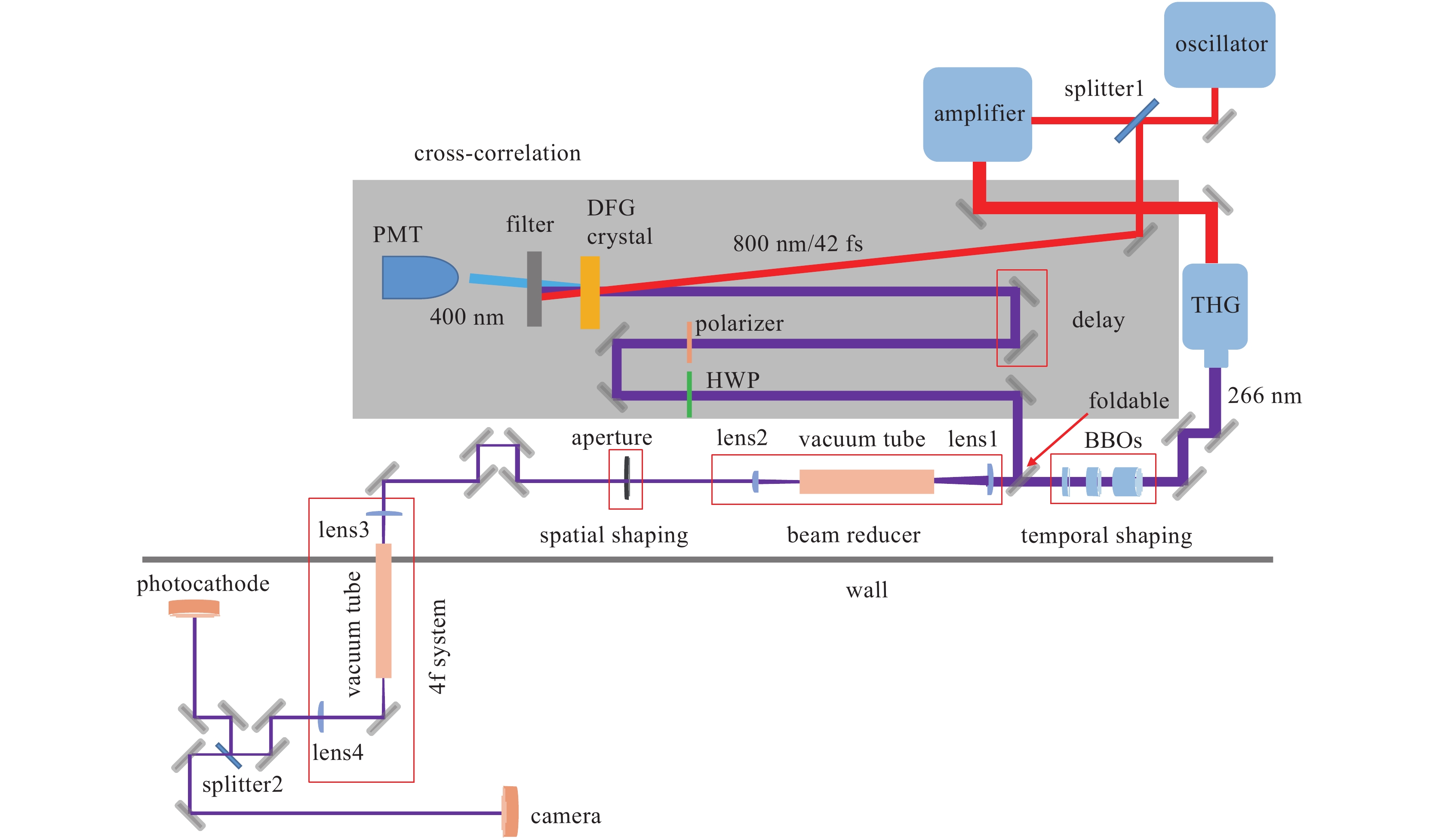
1 Overall layout of the optical system
The laser system (Coherent Inc.) consists of 3 main parts: oscillator, amplifier, and third harmonic generator, and their specific parameters are shown in Table 1 respectively.
| element | wavelength/nm | pulse width/fs | repetition rate/Hz | pulse energy/nJ |
| oscillator | 800 | 42 | 79.33×10⁶ | 9 |
| amplifier | 800 | 103 | 1−100 | 13×106 |
| third harmonic generator | 266.7 | 1.5×10³ | 1−100 | 2×10⁶ |
Table 1. Laser parameters
The overall layout of the optical system is shown in Fig. 1. The oscillator emits a horizontally polarized laser at central wavelength of 800 nm and a pulse width of 42 fs. It is divided into two beams through a 50/50 beam splitter, one of which is used for the cross-correlation scanning measurements, and the other is sent to the amplifier to produce an amplified laser with a pulse width of about 1 ps. The repetition rate of the laser is adjustable in the range of 1−100 Hz. Then the amplified infrared laser pulse passes through a third harmonic generator to produce a 266.7 nm horizontally polarized ultraviolet (UV) laser. The UV laser pulse firstly pass through three α-BBO crystals to form a flat-top distribution in temporal domain.Then a beam reducer is used to reduce the beam size. Downstream the beam reducer, there is a spatial shaping aperture to obtain a truncated-Gaussian profile, which is transported to the photocathode through the 4f system. In the transport system, a 5% beam splitter (i.e. splitter2) is introduced for virtual cathode monitoring.
![]()
Figure 1.Schematic diagram of the overall laser optical system
2 Optical design and experimental results of the pulse shaping and transport system
2.1 Temporal pulse shaping
α-BBO crystal is an excellent birefringent material with high transmittance and large birefringence over the wavelength range of 190−3500 nm. The Sellmeier equations of α-BBO crystal can be expressed as follows
where the unit of λ is µm. The relationship between the group refractive index and the refractive index is
where ng represents the group refractive index, and n represents the refractive index.
Assuming that the angle between the polarization direction of the pulse and the optical axis is Ψ, after passing through the α-BBO crystal, the electric field amplitude ratio of the o-ray (component perpendicular to the optical axis) and e-ray (component parallel to the optical axis) is tanΨ. To ensure that the intensity of the two pulses is equal, Ψ should be +45° or −45°.
Refractive indexes of the two pulses in the crystal are different, which cause their propagation speed to be different, and the temporal separation ∆t introduced by the crystal of length L can be expressed as follows
where vog and veg are the group velocities for the o-ray and e-ray respectively, c is the speed of light in vacuum, and nog and neg are the group index of refraction for the o-ray and e-ray respectively.
For the UV laser at central wavelength 266.7 nm, nog = 2.031 and neg = 1.778. Then it can be calculated as
Generally, using m birefringent crystals can transform a single Gaussian pulse into a stack of 2m Gaussian output pulses. Fig. 2 shows a schematic diagram of temporal shaping using three α-BBO crystals, in which the red line represents the polarization direction of the laser pulse and the optical axis of the crystal. The horizontally polarized laser pulse passes through the first crystal (the optical axis oriented at 45° relative to the horizontal direction) and then it is divided into two sub-pulses with equal intensity. For α-BBO (a negative uniaxial crystal), the e-ray will move ahead of the o-ray. After passing through the second crystal (the optical axis oriented at 90° relative to the horizontal direction), each sub-pulse is divided into two sub-pulses, thus producing four sub-pulses with equal intensity. Finally, the four sub-pulses pass through the third crystal (the optical axis oriented at 45° relative to horizontal direction) to produce eight sub-pulses with alternate polarizations. To get micro-pulses with equal interval, the thickness of the latter crystal should be half or twice as the former one. Here we set the thickness of the first crystal to be L, then the thickness of the second and third crystal to be L/2 and L/4 respectively. According to the width of the initial laser pulse, we design the pulse interval to be 1.512 ps, corresponding to the thickness of the third crystal as 1.8 mm and the total thickness of the three crystals as 12.6 mm. The transmittance of α-BBO crystal will decrease as the thickness of the crystal increases. According to the measurement, the total transmittance of the three crystals is about 45%. The influence of the dispersive material needs to be considered. In the optical system, three kinds of dispersive materials are included: α-BBO crystals used for pulse stacking, CaF2 lenses used for beam reducer and 4f systems, and fused silica windows used at both ends of the vacuum pipe. The total material dispersion was calculated as 0.01039 ps2 and 0.00667 ps2 for the o-ray and e-rayrespectively, which is negligible for ps pulses.
![]()
Figure 2.Schematic diagram of pulse stacking scheme
To measure the temporal distribution precisely, the cross-correlation scanning method is used. In the experiment, using the shaped pulse and an IR pulse to irradiate the β-BBO crystal at a small angle, then a 400 nm signal is generated by difference frequency generation (DFG) in the crystal (type I, o + o = e, 0.2 mm , θ = 46.5°). A half-wave plate and polarizer placed after the stacker enable us to rotate the polarization of the output pulse to match the polarization of the IR pulse. A high-sensitivity photomultiplier tube (PMT) is used to detect the 400 nm signal. The cross-correlation profile is obtained by a multishot measurement scanning the delay of the pulse. We reduce the amplitude jitter by averaging on many shots per delay position. The resolution of the system is limited by the step length of the delay line and the IR pulse width. The minimum step of the translation stage we use can reach 0.05 µm, so the measurement accuracy depends on the IR pulse width is 42 fs.
Fig. 3 shows the theoretical and experimental results. The measured RMS intensity fluctuation of the shaped pulse is 7.7%, the rise time is about 1 ps, and the fall time is about 1.27 ps.
![]()
Figure 3.Temporal profiles of laser pulse
As can be seen in Fig. 3, there is a difference between the theoretical results and experimental results, which comes from several aspects. First, the temporal distribution of the initial pulse is not perfectly Gaussian. Second, the actual thickness of each crystal has a relatively large deviation from the theoretical design. It is best to control the tolerance within ± 0.01 mm. Third, the adjustment precision of the crystal holder is not good enough (only 2°). It is necessary to replace it with a higher-precision crystal rotation holder.
2.2 Spatial pulse shaping and transport system
As shown in Fig. 1, after temporal shaping, the input laser beam is reduced by using a 2.5× beam reducer, and the laser beam radius becomes 2.12 mm (1/e2). Then an aperture with a diameter of 2 mm is used to obtain a truncated-Gaussian profile, which is transported to the photocathode through the 4f system.
We use plano-convex lenses of focal length +160 mm and +400 mm for the beam reducer and two plano-convex lenses of focal length +1500 mm for the 4f system. Simulation results of the laser beam transport system are shown in Fig. 4.
![]()
Figure 4.Designed spatial profiles of laser pulse
It can be seen that the optical components we selected can well transport the truncated-Gaussian pulse to the photocathode.
As shown in Fig. 5, the spatial distribution of the laser pulse is measured at different positions. At the designed position, an image of the pulse transport through the aperture can be observed. At other positions, diffraction patterns appear as a fringe structure imposed on the actual spatial distribution. At the range of plus or minus 5 cm from the designed positions, we can observe that the diffraction is not obvious, which is beneficial to the construction of the optical system.
![]()
Figure 5.Measured transverse distributions (upper) and horizontal cuts (lower) of laser pulse at different positions around the nominal imaging plane. From left to right, the distances to the nominal imaging plane are −5 cm, 0 cm and 5 cm.
At the focal point of the lens, the laser power density is very high, which will cause air ionization. For this reason, we installed a vacuum tube in the focusing light path. Vacuum windows need to be added at both ends of the vacuum tubes. The material of the window needs to be selected with a high damage threshold, and KrF fused silica window can ensure a longer lifetime. Moreover, we found that the damage of the coating film on the window is on the vacuum side. We experimentally found that when the vacuum is on the order of 103 Pa, the window has a longer lifetime.
It can be seen in Fig. 5 that the spatial distribution of the laser pulse is not particularly uniform, which may be caused by dust on the surface of the window or different transmittance at different positions of the vacuum window.
To ensure that the position jitter of the laser is small, an optical image transport system is designed, which ensures that the free transport distance is very short. The test results of monitoring the position and energy of the laser for 1 h per day in different 10 days are shown in Fig. 6. It can be found that the RMS jitter of the laser position is less than 4 µm, and the RMS fluctuation of the laser energy is less than 0.5% (The pulse energy on the photocathode is set at around 50 µJ), which meets the requirements of the photocathode RF gun.
![]()
Figure 6.Measurement results of laser pulse position and energy
3 Conclusion
The optical design and experimental studies on the spatiotemporal shaping of ps laser pulse are presented. 3 α-BBO crystals are used for temporal shaping and an aperture for spatial shaping. A quasi-uniform distribution in three-dimensional space of laser pulse is obtained. Using the image transport system, the final spatiotemporal shaped pulse can be transported to the photocathode at 6 m away from the aperture. In addition, the position and energy jitter of the drive laser at the virtual cathode are also measured. The experimental results show that the RMS jitter of the laser position is less than 4 µm, and the RMS jitter of the energy is less than 0.5%.
References
[1] Akre R, Dowell D, Emma P, et al. Commissioning the linac coherent light source injector[J]. Physical Review Special Topics-Accelerators and Beams, 11, 030703(2008).
[2] Zhu Pengfei, Zhu Y, Hidaka Y, et al. Femtosecond time-resolved MeV electron diffraction[J]. New Journal of Physics, 17, 063004(2015).
[3] Xiang D, Fu F, Zhang J, et al. Accelerator-based single-shot ultrafast transmission electron microscope with picosecond temporal resolution and nanometer spatial resolution[J]. Nuclear Instruments and Methods in Physics Research Section A:Accelerators, Spectrometers, Detectors and Associated Equipment, 759, 74-82(2014).
[4] Yang Jinfeng, Kondoh T, Kozawa T, et al. Pulse radiolysis based on a femtosecond electron beam and a femtosecond laser light with double-pulse injection technique[J]. Radiation Physics and Chemistry, 75, 1034-1040(2006).
[5] Chen Han, Yan Lixin, Tian Qili, et al. Commissioning the photoinjector of a gamma-ray light source[J]. Physical Review Accelerators and Beams, 22, 053403(2019).
[6] Kim K J. RF and space-charge effects in laser-driven RF electron guns[J]. Nuclear Instruments and Methods in Physics Research Section A:Accelerators, Spectrometers, Detectors and Associated Equipment, 275, 201-218(1989).
[7] Serafini L, Rosenzweig J B. Envelope analysis of intense relativistic quasilaminar beams in rf photoinjectors: mA theory of emittance compensation[J]. Physical Review E, 55, 7565-7590(1997).
[8] Schwarz J, Rambo P K, Smith I C, et al. Simple temporal pulse shaping using two Pockels cells[J]. Optical Engineering, 44, 094203(2005).
[9] Sharma A K, Patidar R K, Raghuramaiah M, et al. Simple electro-optic technique to generate temporally flat-top laser pulses[J]. Optics Communications, 284, 4596-4600(2011).
[10] Skeldon M D. Optical pulse-shaping system based on an electro-optic modulator driven by an aperture-coupled-stripline electrical-waveform generator[J]. Journal of the Optical Society of America B, 19, 2423-2426(2002).
[11] Field J J, Durfee III C G, Squier J A, et al. Quartic-phase-limited grism-based ultrashort pulse shaper[J]. Optics Letters, 32, 3101-3103(2007).
[12] Weiner A M. Femtosecond pulse shaping using spatial light modulators[J]. Review of Scientific Instruments, 71, 1929-1960(2000).
[13] Weiner A M. Ultrafast optical pulse shaping: a tutorial review[J]. Optics Communications, 284, 3669-3692(2011).
[14] Loos H, Dowell D, Gilevich S, et al. Tempal Ebeam shaping in an Sb accelerat[C]Proceedings of the 2005 Particle Accelerat Conference. 2005: 642644.
[15] Vicario C, Ghigo A, Cialdi S, et al. Laser tempal pulse shaping experiment f SPARC photoinject[R]. CAREConf04030PHIN, 2004.
[16] Park Y, Asghari M H, Ahn T J, et al. Transform-limited picosecond pulse shaping based on temporal coherence synthesization[J]. Optics Express, 15, 9584-9599(2007).
[17] Wang X T, Feng L, Lan T, et al. Drive laser tempal shaping techniques f Shanghai soft Xray free electron laser[C]39th International Free Electron Laser Conference. 2019: 466468.
[18] Sharma A K, Tsang T, Rao T. Theoretical and experimental study of passive spatiotemporal shaping of picosecond laser pulses[J]. Physical Review Special Topics-Accelerators and Beams, 12, 033501(2009).
[19] Wang Dong, Yan Lixin, Huang Wenhui. UV Pulse shaping with αBBO crystals f the photocathode RF gun[C]Proceedings of the 7th International Particle Accelerat Conference. 2016: 40794081.
[20] Laskin A, Laskin V. Imaging techniques with refractive beam shaping optics[C]Proceedings of SPIE 8490, Laser Beam Shaping XIII. 2012: 84900J.
[21] Laskin A, Laskin V. Beam shaping in highpower laser systems with using refractive beam shapers[C]Proceedings of SPIE 8433, Laser Sources Applications. 2012: 84330N.
[22] Halavanau A, Ha G, Qiang G, et al. Microlens array laser transverse shaping technique f photoemission electron source[DBOL]. arXiv preprint arXiv: 1609.01661, 2016.
[23] Jin Yuhua, Hassan A, Jiang Yijian. Freeform microlens array homogenizer for excimer laser beam shaping[J]. Optics Express, 24, 24846-24858(2016).
[24] Tomizawa H, Dewa H, Taniuchi T, et al. Adaptive 3D UVlaser pulse shaping system to minimize emittance f photocathode RF gun new laser incidence system[C]Proceedings of FEL. 2007: 298305.
[25] Gross M, Qian H J, Boonpornprasert P, et al. Emittance reduction of RF photoinjector generated electron beams by transverse laser beam shaping[J]. Journal of Physics:Conference Series, 1350, 012046(2019).
[26] Zhou Feng, Brachmann A, Emma P, et al. Impact of the spatial laser distribution on photocathode gun operation[J]. Physical Review Special Topics-Accelerators and Beams, 15, 090701(2012).


Set citation alerts for the article
Please enter your email address

© Copyright 2018-2021 | Chinese Laser Press. All Rights Reserved 沪ICP备15018463号-20