
Zhen Yue, Jitao Li, Jie Li, Chenglong Zheng, Jingyu Liu, Guocui Wang, Hang Xu, Mingyang Chen, Yating Zhang, Yan Zhang, Jianquan Yao. Terahertz metasurface zone plates with arbitrary polarizations to a fixed polarization conversion[J]. Opto-Electronic Science, 2022, 1(3): 210014-1
- Opto-Electronic Science
- Vol. 1, Issue 3, 210014-1 (2022)
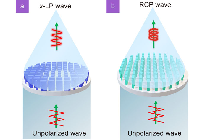
Fig. 1. (a ) Performing diagram of x-LP beam generator. (b ) Schematic diagram of RCP beam generation under non-polarized incidence.
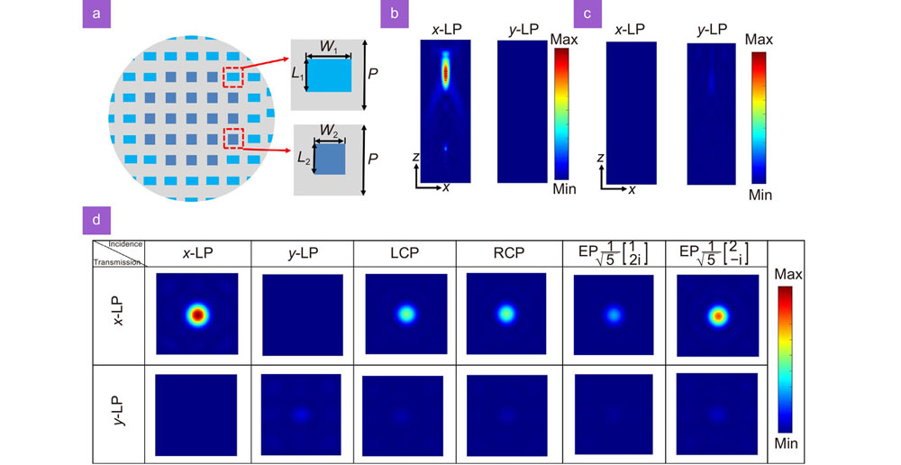
Fig. 2. (a ) Schematic diagram of the linear polarizer. (b ) Simulated results on the xz plane under x-LP incidence. (c ) The intensity distributions of the transmitted x-LP and y-LP components on the xz plane under y-LP illumination. (d ) The intensity profiles of the orthogonal LP components of the outgoing wave at the focal plane, under different polarized incidences.
Fig. 3. (a ) SEM image of the sample. (b ) The measured intensity profiles of x-LP and y-LP components on the focal plane, under the incidences of four polarized waves.
Fig. 4. (a ) Schematic of the Meta-atom 1. (b ) Top view of the Meta-atom 2. (c ) Transmission amplitudes of cross- and co-polarized components at different frequencies, under LCP incidence. (d ) Simulated results of phase shifts under LCP incidence. (e ) The relationship between the transmission amplitudes of the orthogonal CP components and the incident frequency, when the RCP wave is incident. (f ) The phase shift of the transmitted LCP wave at different incident frequencies under RCP incidence.
Fig. 5. (a ) Schematic diagram of the structure of the metasurface zone plate. (b , c ) The intensity distributions of the cross- and co-polarized components at the focal plane under CP incidences. (d ) The simulated intensity distribution of the focal plane under LP and EP incidences.
Fig. 6. (a ) SEM image of the fabricated metasurface zone plate. (b ) The measured intensity profiles of the focal plane under CP and LP incidences. The inset is the intensity distribution across the focus along the x-axis.

Set citation alerts for the article
Please enter your email address
© Copyright 2018-2021 | Chinese Laser Press. All Rights Reserved 沪ICP备15018463号-20