• Photonics Research
  • Vol. 6, Issue 3, 162 (2018)
Qian Zhang1、†, Xuemei Cheng1、†,*, Haowei Chen1、3, Bo He1, Zhaoyu Ren1, Ying Zhang2, and Jintao Bai1
Author Affiliations
  • 1State Key Laboratory Incubation Base of Photoelectric Technology and Functional Materials, National Photoelectric Technology and Functional Materials and Application of Science and Technology International Cooperation Center, Institute of Photonics & Photon-Technology, Northwest University, Xi’an 710069, China
  • 2School of Science, Engineering University of PAP, Xi’an 710086, China
  • 3e-mail: chenhaowei2005@126.com
  • show less
    DOI: 10.1364/PRJ.6.000162 Cite this Article Set citation alerts
    Qian Zhang, Xuemei Cheng, Haowei Chen, Bo He, Zhaoyu Ren, Ying Zhang, Jintao Bai. Enhancement of phase conjugation degenerate four-wave mixing using a Bessel beam[J]. Photonics Research, 2018, 6(3): 162 Copy Citation Text show less
    Scheme of the experimental setup. The insert located at the bottom left is the energy-level diagram we employed in which |a⟩ and |b⟩ stand for |5S1/2,F=3⟩ of Rb85 and |5P3/2,F=2,3,4⟩ of Rb85, respectively. The insert at the bottom right is the phase-matching configuration of the DFWM process. The coordinate z stands for the propagating direction of the probe beam originated from Lens5. The obstruction is inserted at z=445 mm, and the Rb cell is set with its right side at z=460 mm. Ti:S laser, Ti:sapphire laser; HWP, half-wave plate; HR, highly reflective mirror; PBS, polarization beam splitter; Obs, obstruction; Si:D, silicon detector. Ethanol is contained in a cuvette.
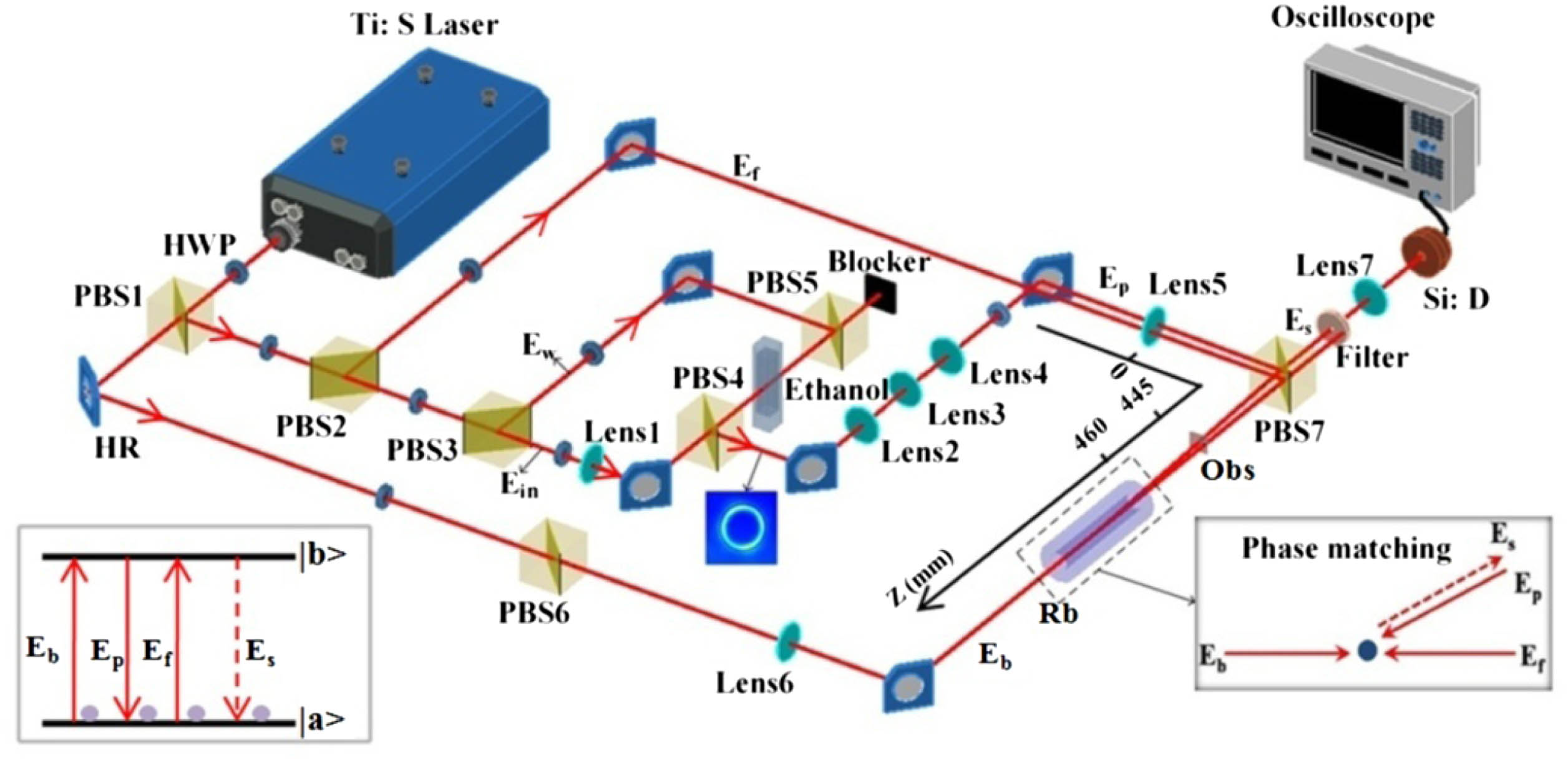
    Fig. 1. Scheme of the experimental setup. The insert located at the bottom left is the energy-level diagram we employed in which |a and |b stand for |5S1/2,F=3 of Rb85 and |5P3/2,F=2,3,4 of Rb85, respectively. The insert at the bottom right is the phase-matching configuration of the DFWM process. The coordinate z stands for the propagating direction of the probe beam originated from Lens5. The obstruction is inserted at z=445  mm, and the Rb cell is set with its right side at z=460  mm. Ti:S laser, Ti:sapphire laser; HWP, half-wave plate; HR, highly reflective mirror; PBS, polarization beam splitter; Obs, obstruction; Si:D, silicon detector. Ethanol is contained in a cuvette.
    Enhancement of DFWM signal with hollow input probe beam compared with Gaussian input. (a) Spectra of DFWM signal with hollow and Gaussian beams as the probe beam; (b) DFWM signal images with hollow beam (upper) and Gaussian beam (bottom) at the wavelength of 780.2424 nm, resonant to the transition |5S1/2,F=3⟩→|5P3/2⟩ of Rb85. The laser powers of Eb, Ef, and Ep were set at 5, 20, and 20 mW, respectively, and the temperature of the Rb cell was set at 40°C.
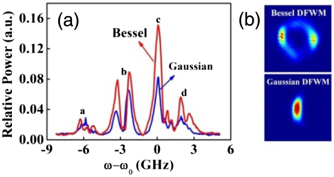
    Fig. 2. Enhancement of DFWM signal with hollow input probe beam compared with Gaussian input. (a) Spectra of DFWM signal with hollow and Gaussian beams as the probe beam; (b) DFWM signal images with hollow beam (upper) and Gaussian beam (bottom) at the wavelength of 780.2424 nm, resonant to the transition |5S1/2,F=3|5P3/2 of Rb85. The laser powers of Eb, Ef, and Ep were set at 5, 20, and 20 mW, respectively, and the temperature of the Rb cell was set at 40°C.
    Comparison of the light propagation properties between Gaussian and Bessel beams. (a) Images of Bessel beam (top row) and Gaussian beam (bottom row) at various positions along the propagation coordinate z in the focusing range. (b) The radius of the central spot of the Bessel beam and the Gaussian beam at various positions along the propagation coordinate z in the focusing range; (c) and (d) show the lateral intensity distribution of the Bessel beam and the Gaussian beam at z=440 mm and z=560 mm, respectively. The power of probe beam Ep was fixed at 1 mW, the laser wavelength was kept at 780.2424 nm, and the temperature of the Rb cell was set at 40°C.
    Fig. 3. Comparison of the light propagation properties between Gaussian and Bessel beams. (a) Images of Bessel beam (top row) and Gaussian beam (bottom row) at various positions along the propagation coordinate z in the focusing range. (b) The radius of the central spot of the Bessel beam and the Gaussian beam at various positions along the propagation coordinate z in the focusing range; (c) and (d) show the lateral intensity distribution of the Bessel beam and the Gaussian beam at z=440  mm and z=560  mm, respectively. The power of probe beam Ep was fixed at 1 mW, the laser wavelength was kept at 780.2424 nm, and the temperature of the Rb cell was set at 40°C.
    Enhancement of DFWM signal with hollow input probe beam compared with Gaussian input when the probe beam encounters an obstruction on its propagation way to the Rb sample. (a) Spectra of DFWM signal with hollow and Gaussian beams as the probe beam; (b) DFWM signal images with hollow beam (upper) and Gaussian beam (bottom) at the wavelength of 780.2424 nm, resonant to the transition |5S1/2,F=3⟩→|5P3/2⟩ of Rb85. The laser powers of Eb, Ef, and Ep were set at 5, 20, and 20 mW, respectively, and the temperature of the Rb cell was set at 40°C.
    Fig. 4. Enhancement of DFWM signal with hollow input probe beam compared with Gaussian input when the probe beam encounters an obstruction on its propagation way to the Rb sample. (a) Spectra of DFWM signal with hollow and Gaussian beams as the probe beam; (b) DFWM signal images with hollow beam (upper) and Gaussian beam (bottom) at the wavelength of 780.2424 nm, resonant to the transition |5S1/2,F=3|5P3/2 of Rb85. The laser powers of Eb, Ef, and Ep were set at 5, 20, and 20 mW, respectively, and the temperature of the Rb cell was set at 40°C.
    Self-reconstruction of the Bessel beam and the Gaussian beam. (a) Images of the Bessel beam (upper row) and the Gaussian beam (bottom row) at various positions along the propagation coordinate z when the Gaussian beam and the Bessel beam pass through obstruction; (b)–(d) show the lateral intensity distribution of the Bessel beam and the Gaussian beam at z=440 mm, z=500 mm, and z=560 mm. The power of probe beam Ep was fixed at 1 mW, the laser wavelength was kept at 780.2424 nm, the temperature of the Rb cell was set at 40°C, and the obstruction was set at z=445 mm.
    Fig. 5. Self-reconstruction of the Bessel beam and the Gaussian beam. (a) Images of the Bessel beam (upper row) and the Gaussian beam (bottom row) at various positions along the propagation coordinate z when the Gaussian beam and the Bessel beam pass through obstruction; (b)–(d) show the lateral intensity distribution of the Bessel beam and the Gaussian beam at z=440  mm, z=500  mm, and z=560  mm. The power of probe beam Ep was fixed at 1 mW, the laser wavelength was kept at 780.2424 nm, the temperature of the Rb cell was set at 40°C, and the obstruction was set at z=445  mm.
    Qian Zhang, Xuemei Cheng, Haowei Chen, Bo He, Zhaoyu Ren, Ying Zhang, Jintao Bai. Enhancement of phase conjugation degenerate four-wave mixing using a Bessel beam[J]. Photonics Research, 2018, 6(3): 162
    Download Citation