
Ruidi ZHANG, Yaxuan DUAN, Zhengshang DA. High Quality Bessel Beam Array Generation Method Based on Computer Generated Holography[J]. Acta Photonica Sinica, 2023, 52(9): 0909001
- Acta Photonica Sinica
- Vol. 52, Issue 9, 0909001 (2023)
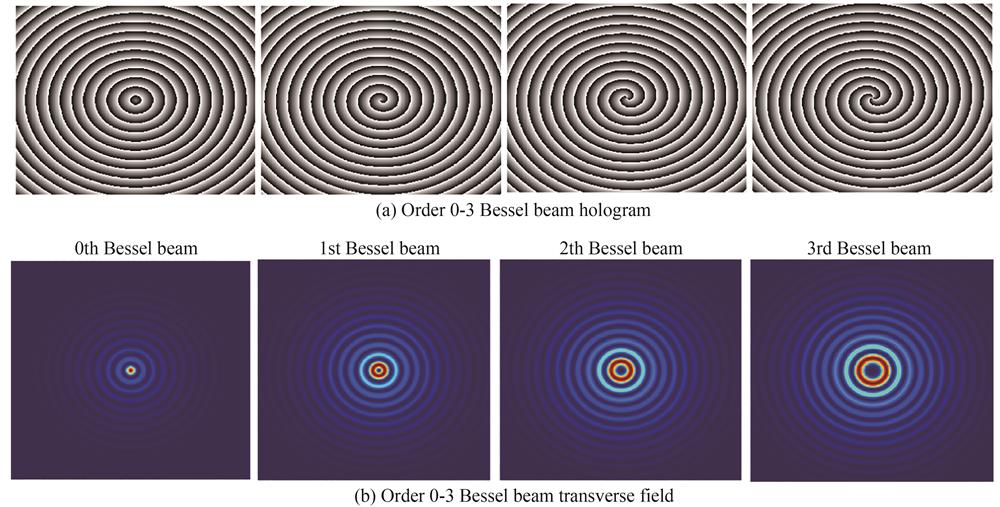
Fig. 1. Holograms of 0~3 order Bessel beams and transverse light fields
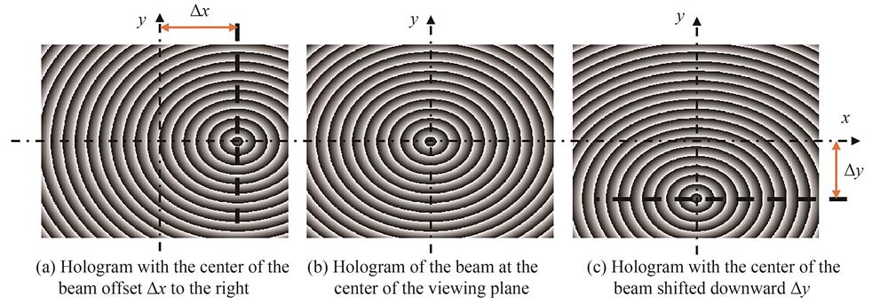
Fig. 2. Hologram of Bessel beams at different positions
Fig. 3. Schematic diagram of parallel splicing method
Fig. 4. Schematic diagram of Dammann grating and axicon phase superposition method
Fig. 5. Schematic diagram of optical path
Fig. 6. 3×3 Bessel beam array hologram obtained by the proposed method and the traditional method
Fig. 7. 3D and 2D images and transverse profile of light intensity of Bessel beam array generated by the proposed method and the traditional method
Fig. 8. The diffraction pattern of Bessel beam array generated by the proposed method and the traditional method at 120 mm,130 mm and 140 mm positions along the transmission direction
Fig. 9. The light intensity profile of the proposed method and the traditional method at 120 mm,130 mm and 140 mm positions along the transmission direction
Fig. 10. The sectional field distribution of Bessel beam array along the transmission direction generated by the proposed method and the traditional method
Fig. 11. Experimental light path diagram
Fig. 12. The experimental results of Bessel beam array generated by the proposed method and the traditional method at 120 mm,130 mm and 140 mm positions along the transmission direction
|
Table 1. The maximum diffract-free distance,uniformity and diffraction efficiency of Bessel beam arrays produced by the proposed method and the traditional method

Set citation alerts for the article
Please enter your email address
© Copyright 2018-2021 | Chinese Laser Press. All Rights Reserved 沪ICP备15018463号-20