
Lei-Jie Zhu, Fa-Qiang Wang. Design and analysis of new meminductor model based on Knowm memristor [J]. Acta Physica Sinica, 2019, 68(19): 198501-1
- Acta Physica Sinica
- Vol. 68, Issue 19, 198501-1 (2019)
Fig. 1. Symbol of Knowm memristor.Knowm忆阻器符号
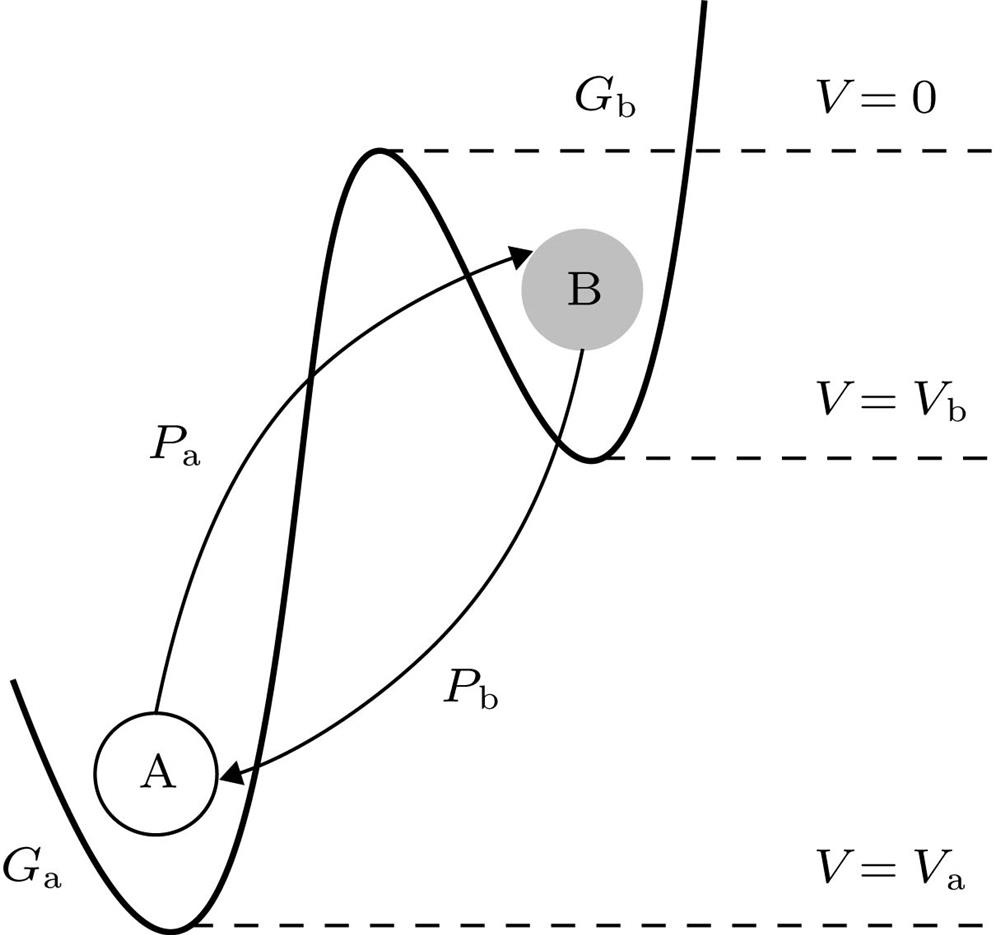
Fig. 2. Theoretical model of Knowm memristor.Knowm忆阻器的理论模型
Fig. 3. Emulator circuit for meminductor.忆感器模拟电路图
Fig. 4. relationship diagram under different parameters: (a)
= 100—140 Hz,
= 1.62 mA/V; 11. (b)
= 240—400 Hz,
= 1.62 mA/V; (c)
= 500—1400 Hz,
= 1.62 mA/V; (d)
= 120 Hz,
=1.49—1.97 mA/V.
不同参数情况下的
关系图 (a)
= 100—140 Hz,
= 1.62 mA/V; (b)
= 240—400 Hz,
= 1.62 mA/V; (c)
= 500—1400 Hz,
= 1.62 mA/V; (d)
= 120 Hz,
= 1.49—1.97 mA/V
Fig. 5. relationship diagram under different Knowm memristor parameters: (a)
,
; (b)
,
.
不同Knowm忆阻器参数情况下的
关系图 (a)
,
; (b)
,
Fig. 6. Wiring diagram for the experiment.实验接线图
Fig. 7. relationship diagram under different parameters. The first channel is
, and the second channel is
: (a)
= 100 Hz,
= 1.62 mA/V; (b)
= 120 Hz,
= 1.62 mA/V; (c)
= 140 Hz,
= 1.62 mA/V; (d)
= 120 Hz,
= 1.49 mA/V.
不同参数作用下的
关系图, 其中第一通道为
, 第二通道为
(a)
= 100 Hz,
= 1.62 mA/V; (b)
= 120 Hz,
= 1.62 mA/V; (c)
= 140 Hz,
= 1.62 mA/V; (d)
= 120 Hz,
= 1.49 mA/V
|
Table 1. Component parameter values used in LTspice simulation circuits.

Set citation alerts for the article
Please enter your email address
© Copyright 2018-2021 | Chinese Laser Press. All Rights Reserved 沪ICP备15018463号-20