Author Affiliations
National Key Laboratory of Electromagnetic Environment Effects, Army Engineering University (Shijiazhuang Campus), Shijiazhuang 050003, Chinashow less
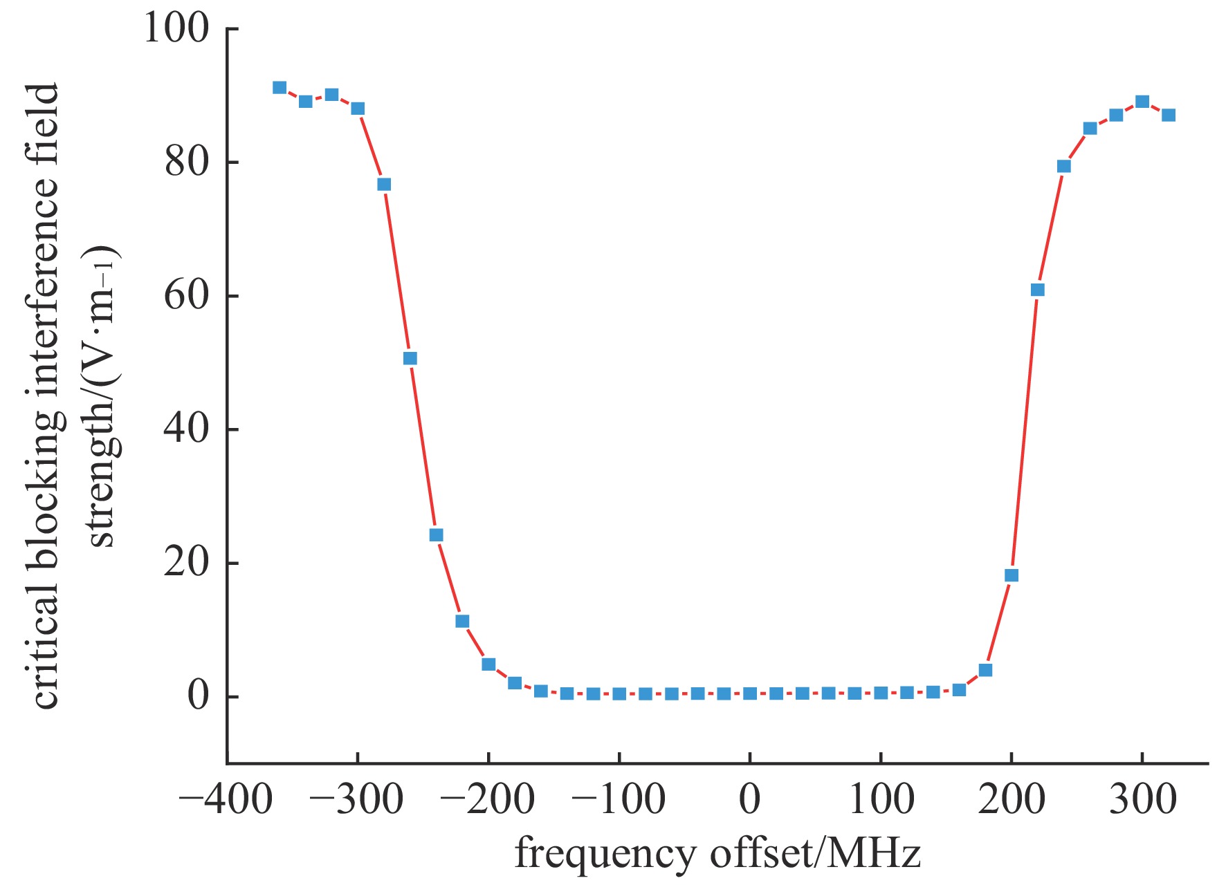
Fig. 1. Critical blocking interference field strength of single frequency electromagnetic radiation of the tested radar
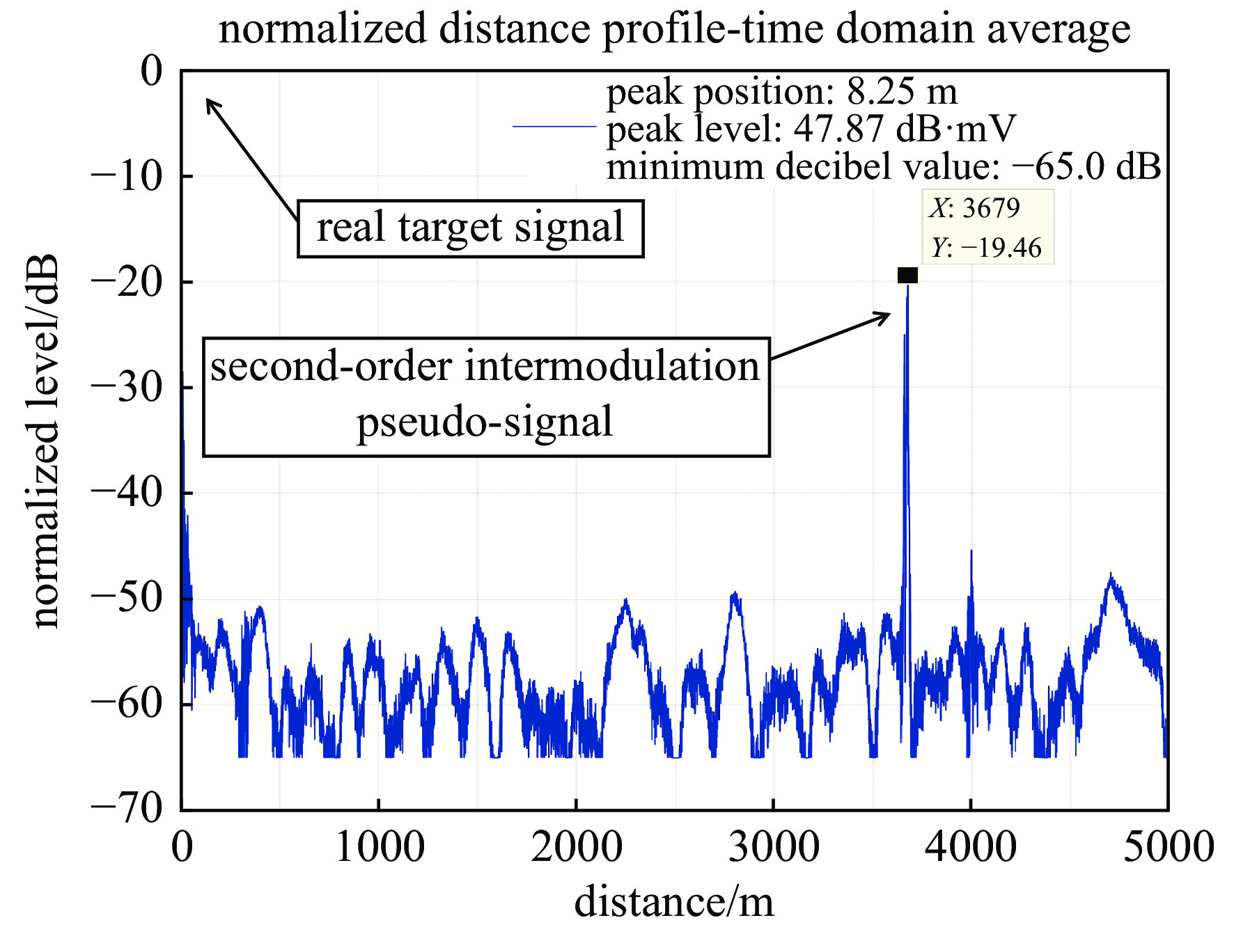
Fig. 2. Radar detection target imaging under dual-frequency electromagnetic radiation
Fig. 3. Variation curve of second-order intermodulation pseudo-signal with interference field strength
Fig. 4. Change of second-order intermodulation pseudo-signal level with radiation frequency difference when the interference field strength is fixed
Fig. 5. Change of second-order intermodulation pseudo-signal interference factor with radiation frequency offset
Fig. 6. Curve of the relative value of the low-frequency pseudo-signal level with the second-order cross-frequency modulation difference
Δfi/MHz
| Ei0/(V·m−1)
| | Δfi/MHz
| Ei0/(V·m−1)
| | Δfi/MHz
| Ei0/(V·m−1)
| | Δfi/MHz
| Ei0/(V·m−1)
| | Δfi/MHz
| Ei0/(V·m−1)
| −320 | 90.2 | | −180 | 2.1 | | −40 | 0.5 | | 100 | 0.6 | | 240 | 79.4 | −300 | 88.1 | | −160 | 0.9 | | −20 | 0.5 | | 120 | 0.7 | | 260 | 85.1 | −280 | 76.7 | | −140 | 0.5 | | 0 | 0.5 | | 140 | 0.8 | | 280 | 87.1 | −260 | 50.7 | | −120 | 0.5 | | 20 | 0.5 | | 160 | 1.1 | | 300 | 89.1 | −240 | 24.3 | | −100 | 0.5 | | 40 | 0.5 | | 180 | 4.0 | | 320 | 87.1 | −220 | 11.4 | | −80 | 0.5 | | 60 | 0.6 | | 200 | 18.2 | | − | − | −200 | 4.9 | | −60 | 0.5 | | 80 | 0.6 | | 220 | 60.9 | | − | − |
|
Table 1. Fitting values of single frequency electromagnetic radiation critical blocking interference field strength
Δfi/MHz
| $ \;{ \beta _{\text{F}}}(\Delta {f_i}) $![]() /dB
| | Δfi/MHz
| $ \;{ \beta _{\text{F}}}(\Delta {f_i}) $![]() /dB
| | Δfi/MHz
| $ \;{ \beta _{\text{F}}}(\Delta {f_i}) $![]() /dB
| | Δfi/MHz
| $ \;{ \beta _{\text{F}}}(\Delta {f_i}) $![]() /dB
| −340 | 10.3 | | −160 | 11.4 | | 20 | 12.8 | | 200 | 10.8 | −320 | 10.5 | | −140 | 11.9 | | 40 | 13.0 | | 220 | 10.4 | −300 | 10.5 | | −120 | 12.4 | | 60 | 13.2 | | 240 | 10.2 | −280 | 10.4 | | −100 | 12.7 | | 80 | 13.3 | | 260 | 10.2 | −260 | 10.3 | | −80 | 12.8 | | 100 | 13.3 | | 280 | 10.2 | −240 | 10.2 | | −60 | 12.8 | | 120 | 13.0 | | 300 | 10.3 | −220 | 10.2 | | −40 | 12.7 | | 140 | 12.5 | | 320 | 10.2 | −200 | 10.4 | | −20 | 12.6 | | 160 | 11.9 | | 340 | 10.1 | −180 | 10.8 | | 0 | 12.6 | | 180 | 11.3 | | 360 | 9.9 |
|
Table 2. Test results of second-order intermodulation pseudo-signal interference factor
\begin{document}$ \;{ \beta _{\text{F}}}(\Delta {f_i}) $\end{document}![]()
|Δf|/MHz
| Xr(∆f)/dB
| | |Δf|/MHz
| Xr(∆f)/dB
| | |Δf|/MHz
| Xr(∆f)/dB
| | |Δf|/MHz
| Xr(∆f)/dB
| | |Δf|/MHz
| Xr(∆f)/dB
| 0.1 | 0.4 | | 0.7 | 0.0 | | 1.3 | 2.4 | | 1.9 | 6.3 | | 2.5 | 11.5 | 0.2 | 0.5 | | 0.8 | 0.0 | | 1.4 | 3.0 | | 2 | 7.1 | | 2.6 | 12.9 | 0.3 | 0.4 | | 0.9 | 0.2 | | 1.5 | 3.7 | | 2.1 | 7.9 | | 2.7 | 14.7 | 0.4 | 0.4 | | 1 | 0.5 | | 1.6 | 4.3 | | 2.2 | 8.7 | | 2.8 | 16.9 | 0.5 | 0.2 | | 1.1 | 1.0 | | 1.7 | 4.9 | | 2.3 | 9.5 | | 2.9 | 19.6 | 0.6 | 0.1 | | 1.2 | 1.7 | | 1.8 | 5.6 | | 2.4 | 10.4 | | 3 | 22.7 |
|
Table 3. Test results of low frequency pseudo signal level relative value Xr(∆f)
criterion/dBmV | Δf1/MHz
| Δf2/MHz
| βF(Δf1)= βF(Δf2)
| Xr(0.6M)
| $ (\dfrac{{E}_{1}}{{E}_{10}}\text{.}\dfrac{{E}_{2}}{{E}_{20}})\text{/dB} $![]() ![]() | RFS2/dB
| 6 | −0.6 | 0 | 12.6 | 0.1 | −30.5 | 0.6 | −0.3 | 0.3 | 12.6 | 0.1 | −32.1 | −1.0 | 0 | 0.6 | 12.6 | 0.1 | −30.2 | 0.9 | 18 | −0.6 | 0 | 12.6 | 0.1 | −18.6 | 0.5 | −0.3 | 0.3 | 12.6 | 0.1 | −19.1 | 0 | 0 | 0.6 | 12.6 | 0.1 | −18.9 | 0.2 |
|
Table 4. Interference effect evaluation of second-order intermodulation pseudo-signal under different sensitive levels
Δfi/MHz
| βF(Δf2)
| $ (\dfrac{{E}_{1}}{{E}_{10}}\text{.}\dfrac{{E}_{2}}{{E}_{20}})\text{/dB} $![]() ![]() | RFS2/dB
| −300 | 10.5 | −19.1 | −1.1 | −200 | 10.4 | −18.0 | −0.2 | −100 | 12.7 | −22.4 | 0 | 0 | 12.6 | −22.0 | 0.2 | 100 | 13.3 | −23.5 | 0.1 | 200 | 10.8 | −19.7 | −1.1 | 300 | 10.3 | −15.7 | 1.9 |
|
Table 5. Interference effect evaluation of second-order intermodulation pseudo-signal in large radiation frequency offset range
|Δf|/MHz
| βF(Δf2)
| Xr(∆f)/dB
| $(\dfrac{ {E}_{1} }{ {E}_{10} }\text{.}\dfrac{ {E}_{2} }{ {E}_{20} })\text{/dB}$![]() ![]() | RFS2/dB
| 0.6 | 12.6 | 0.1 | −21.5 | 0.6 | 1.2 | 12.6 | 1.7 | −19.6 | 0.9 | 1.8 | 12.6 | 5.6 | −17.1 | −0.5 | 2.4 | 12.6 | 10.4 | −13.5 | −1.7 | 3.0 | 12.6 | 22.7 | 3.0 | 2.5 |
|
Table 6. Interference effect evaluation of second-order intermodulation pseudo-signal with large intermodulation frequency difference range