
Yongheng Mu, Cheng Pang, Yuzhong Wang, Qiming Wang, Jiaran Qi, "Complex-amplitude radiation-type metasurface enabling beamform-controlled energy allocation," Photonics Res. 11, 986 (2023)
- Photonics Research
- Vol. 11, Issue 6, 986 (2023)
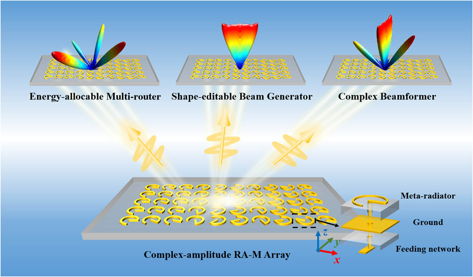
Fig. 1. Schematic function demonstration of the proposed complex-amplitude RA-M. Beams with different characteristics can be obtained based on the proposed strategy. The inset illustrates the detailed structure of the meta-radiator in the dashed box.
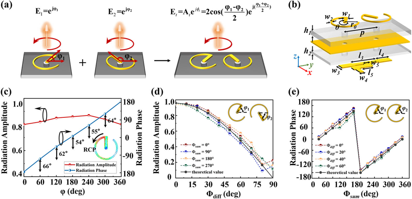
Fig. 2. (a) Schematic principle of the complex-amplitude modulation capability. (b) Schematic diagram of the meta-radiator. (c) Simulated radiation amplitude and radiation phase at 10 GHz when the single ESRR rotates from 0° to 360° and the inset shows the surface current distribution of the single ESRR. (d) and (e) Simulated complex-amplitude modulation of dual SRRs with different rotation angles φ 1 φ 2 Φ sum Φ diff − 180 ° to 180 ° Φ diff Φ sum
Fig. 3. Principle of the proposed far-field complex-amplitude retrieval (FCAR) method: the complex-amplitude iteration (CAI) consists of two processes, amplitude iteration (AI) and phase iteration (PI). The input information contains the preset of the scattered field plane and initial amplitude and phase in the aperture field plane. The initial value of amplitude or phase used in the PI or AI is the final value obtained during the previous iteration and remains constant throughout the iterative process. SSE is used as a criterion to judge the degree of convergence of the iteration. Here, the schematic diagram of the first CAI and the evolution of the scattered field are provided.
Fig. 4. Performance of the functional devices. The 2D patterns of the simulation results are given, and the inset gives the 3D patterns of the calculated results. In particular, the distribution of amplitude, phase, and the rotation angles of Case 1 is added. Energy-controllable multi-router: (a) two channels show a 44° beam with 0 dB and a − 15 ° − 6.2 dB − 10 ° − 3.1 dB − 35 ° − 4.2 dB − 20 ° − 0.8 dB − 3.8 dB − 50 ° − 19 ° − 4.2 dB − 4.9 dB − 0.2 dB − 32 ° − 24 ° − 0.79 dB − 3.79 dB − 7.1 dB − 35 ° − 1.9 dB φ = 0 ° − 19 ° φ = 90 °
Fig. 5. (a) Schematic of the experimental setup for far-field measurement and the front and back views of fabricated RA-M’s photographs. (b) and (e) The 2D simulation (solid black) and measurement (red dashed) far-field results of four-channel energy-allocable multi-router named Sample I. (c) and (f) The 2D simulation and measurement far-field results of shape-editable beams generator named Sample II. (d) and (g) The 2D simulation and measurement far-field results of complex beamformer named Sample III. Black line indicates simulation results, and red dashed line indicates experimental results.
Fig. 6. (a) Simulated radiation amplitude of S 11 Φ sum Φ diff
Fig. 7. (a)–(c) Schematic diagram of the Floquet boundary conditions setting and surface currents distribution of Case 1–Case 3 when ESRR 1 S 11 S 21
Fig. 8. Broadband radiation amplitude and phase characteristics of the two ESRRs. (a)–(d) Broadband radiation amplitude ranging from 9 to 11 GHz when Φ sum Φ diff
Fig. 9. 2D far-field patterns of four two-channel energy-allocable routers and four shape-editable beams generators are given; the inset gives the 3D patterns of the calculated results.
Fig. 10. Simulated amplitude of S 11
Fig. 11. Effect of array size on fan beam where the array size changes from 8 × 8 32 × 32
Fig. 12. Simulated and measured gain characteristics of Sample I–Sample III.


Set citation alerts for the article
Please enter your email address

© Copyright 2018-2021 | Chinese Laser Press. All Rights Reserved 沪ICP备15018463号-20