Abstract
We demonstrate a tunable terahertz (THz) absorber based on an indium tin oxide (ITO) metamaterial. The upper ITO cross-shaped metasurface with different arm lengths is fabricated by direct femtosecond laser etching. The thickness of the middle dielectric layer is only 60 μm, which makes the absorber very transparent and flexible. The experimental results show that the THz resonant peaks have a high performance near 1 THz. By setting spacers of different thicknesses between the middle layer and the ITO mirror, a new type of tunable THz absorber is proposed. Its absorption peak frequency can be continuously adjusted from 0.92 to 1.04 THz between TE and TM polarization. This transparent THz metamaterial absorber is expected to be widely used in THz imaging, sensing, and biological detection.The terahertz (THz) spectrum usually refers to electromagnetic waves between 0.1 and 10 THz. Owing to the low photon energy, strong penetration, and good directivity of THz radiation, THz technology has been widely used in applications such as medical imaging, security detection, and high-speed broadband communication[1–3]. Since metamaterial absorbers were proposed in 2008[4,5], a variety of metamaterial absorbers have endlessly emerged, and their performances have been greatly improved. A THz metamaterial absorber (TMA) is a device that can effectively absorb radiation in the THz range, and it is also a promising component in THz detectors, imagers, and sensors[6–10].
Most traditional THz absorbers use inflexible metamaterials, which limits their application prospects. In 2012, Iwaszczuk et al. developed flexible TMAs that wrapped around a cylinder for stealth[11]. Multispectral THz sensing with a highly flexible ultrathin metamaterial absorber was demonstrated[12], but these absorbers are not easy to tune. In 2013, Hu et al. presented a dynamically tunable THz narrowband metamaterial absorber that is based on an electrostatically actuated micro-electro-mechanical systems (MEMS) cantilever and a split ring resonator (SRR) array[13]. Wang et al. used a few-layer porous graphene and a metasurface as a combined electrode and demonstrated a high efficiency tunable THz absorber based on a large birefringence liquid crystal in 2017[14]. However, most tunable THz absorbers are not flexible[15–20]. The realization of flexibility and tunability on TMA at the same time is expected.
In addition to flexibility and tunability, transparency is also highly favored for practical applications. In 2019, Zhang et al. demonstrated a conformal broadband millimeter metamaterial absorber with a good optical transparency (80.1%)[21]. Recently, Zarbakhsh et al. designed a transparent circularly polarized antenna subarray integrating with a cube satellite’s solar panels. The transparency of the antenna greatly facilitates the solar panel to obtain power[22]. Excellent visual transparency makes this kind of device applicable to building windows, optical flat panels, mobile device displays, etc. Unfortunately, in the TMA field, to date there have been no existing cases of transparent, tunable, and flexible absorbers.
Sign up for Chinese Optics Letters TOC. Get the latest issue of Chinese Optics Letters delivered right to you!Sign up now
Here, we propose a new type of transparent and tunable THz absorber based on flexible metamaterials. It can achieve good absorption of THz radiation at about 1 THz. The THz absorber not only has a good flexibility, but also possesses an excellent optical transmittance. After analyzing the effects of the angle of the crossed indium tin oxide (ITO) arms and the thickness of the polyethylene terephthalate (PET) dielectric layer on absorption performances, we obtain the optimal structure of the absorber. By adding spacers between the PET dielectric layer and the ITO bottom layer, the tunability of the resonant absorption peak from 0.92 to 1.04 THz can be realized.
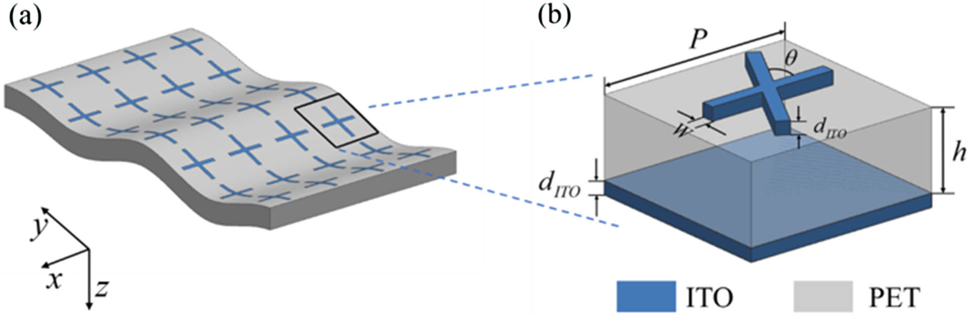
Figure 1(a) shows the structure of the transparent and flexible TMA, which consists of a metasurface layer, an intermediate PET dielectric layer, and an ITO bottom layer. The metasurface is composed of an array of two ITO arms with different lengths. The unit structure of the TMA is shown in Fig. 1(b), where the lengths of the two ITO arms are 100 μm and 120 μm, respectively. The angle between the two arms is , the width of the arm is 10 μm, and the period of the basic structural unit is 150 μm. The thicknesses of the ITO metasurface layer and the ITO bottom layer are both 200 nm. The thickness of the intermediate dielectric layer is and its dielectric constant is . A perfect electric conductor (PEC) is used to simulate the ITO (behaving like metal in THz region), while the ohmic loss is effectively put in the PET. Its working principle is the same as the ordinary tunable TMA[23]. After the metasurface is strongly coupled with the incident THz electric field, the metasurface is paired with the ITO bottom layer. Both the ITO arm itself and the dielectric loss of the PET dielectric layer consume the incident energy. Here, for convenience, we define TE waves as electromagnetic waves with a THz electric field parallel to the x axis, and TM waves as electromagnetic waves with a THz electric field parallel to the y axis.

Figure 1.(a) Schematic of the flexible and transparent TMA. (b) The geometry of a unit cell.
By changing the angle between the two ITO arms of the metasurface, we can effectively adjust the absorption property of the THz absorber. Therefore, we can compare the absorption spectra of the absorbers with different angles to find the optimal . We use a commercial electromagnetic solver (CST Microwave Studio 2018) to investigate. We set the thickness of the PET dielectric layer as 50 μm. Figures 2(a) and 2(b) are the simulated absorption spectrum diagrams with different angles in TE polarization and TM polarization, respectively. We find that the absorption peak is highest when the angle is 90°, especially in TM polarization, and the Q of the TMA is better than at other angles in this situation. The Q factor we use here is equal to the ratio of the resonance frequency to the bandwidth. The electric field distributions at a plane 1 μm above the cross-shaped metasurface with of 60° and 90° are shown in Fig. 2(c). The frequency of the electric field distribution in TE polarization is 0.977 THz, while that in TM polarization is 1.142 THz and 0.926 THz, respectively. By comparison, it is found that the electric fields of the crossed ITO arm are mutually coupled when the angle is 60°, while the arms do not interact with each other when the angle is 90°. This proves that the Q values in both the TE and TM polarizations are better when the angle is 90°. In Fig. 2(d), we give the antiparallel surface a current distribution between the crossed ITO arm resonator and the ITO bottom layer in the TE polarization, which agrees with the TMA operating principle.
Figure 2.(a), (b) Simulated absorptivity spectra of the proposed TMA under TE (TM) polarization with different . (c) Simulated electric field distribution of a unit cell under 60° and 90°. (d) Simulated surface current distribution between the crossed ITO arm resonator and the bottom layer at 0.977 THz in TE polarization.
We further determine the optimal thickness of the intermediate dielectric layer. By setting different dielectric layer thicknesses for simulation, we get the absorption spectrum diagrams shown in Figs. 3(a) and 3(b), which represent the absorption spectra of different dielectric layer thicknesses in TE polarization and TM polarization, respectively. It is easy to find that the absorption peak position of 30 μm has the largest shift from TE polarization to TM polarization, but it is difficult to fabricate. The change of 90 μm in the two polarizations is not obvious. In contrast, the change of 60 μm is acceptable. It is achievable to make the TMA for flexibility and transparency when the thickness is 60 μm.
Figure 3.(a), (b) Simulated absorptivity spectra of the proposed TMA in TE (TM) polarization with different thicknesses.
We first use AutoCAD to design the cross-shaped structure drawing and then use a femtosecond laser system to etch away the redundant ITO part from the 60 μm thick ITO-PET film based on the designed structure with a precision of about 5 μm. The femtosecond laser direct processing technology is a cost-effective, maskless, and scalable manufacturing technology that has been widely used to effectively modify the optical, electrical, and mechanical properties of materials[24]. Finally, a layer of transparent ITO film as the bottom mirror layer is combined to constitute the TMA. The sample after preparation is shown in Fig. 4(a). The middle area of the sample is an ITO metasurface and the surrounding edge is ITO. It can be seen that the middle is more transparent than the edge. We use a multimeter to measure the resistance. The edge resistance is about , while the middle ITO metamaterial shows OL , indicating that this part is insulated. The bent sample is shown in Fig. 4(b), which proves that the absorber is not only flexible but also transparent in the visible range. Figure 4(c) shows the front view of the ITO cross observed with a microscope. The lengths of the two ITO arms are measured. One arm parallel to the x axis shown in Fig. 1 is about 100 μm and the other parallel to the y axis is about 120 μm.
Figure 4.(a) Photograph of the fabricated sample. (b) Photograph of the fabricated sample in the bending state. (c) Cross resonator in a microscope with the reflection mode. , .
The time-domain results of the sample are measured using a THz time-domain spectroscopy (TDS) system (Advantest TAS7400SP) with a reflection analysis accessory shown in Fig. 5(a). The black curve represents the time-domain spectrum of the THz signal source as a reference signal. The red and blue curves represent the time-domain spectrum results of the THz absorber when TE and TM waves are incident, respectively. We can see that the time-domain waveform of the TM is ahead of that of TE. After a Fourier transform, the results of the absorbance spectra are shown in Fig. 5(b). The red absorption curve corresponds to the TE absorption and the blue absorption curve corresponds to the TM absorption. The resonant peak of the absorption curve of the TE wave is located at 1.14 THz and that of the TM wave is located at 1.05 THz. The peak value of the TE wave is higher than that of the TM wave. As shown in Figs. 3(a) and 3(b), the simulated peak of the absorption curve of the TE wave is located at 1.06 THz, and the peak of the absorption curve of the TM wave is located at 1.00 THz. The experimental results in Fig. 5(b) are in good agreement with the simulation results in Fig. 3, which proves that the absorber can indeed efficiently absorb THz waves well.
Figure 5.(a) Time-domain results of the THz absorber. (b) Absorptivity spectra of the proposed TMA from 0.5 to 2.0 THz for TE and TM waves.
The extended structure of the THz absorber is proposed by adding an air layer between the middle PET dielectric layer and the ITO bottom layer. The thickness of the air can be adjusted by different spherical spacers, as shown in Fig. 6(a). The tunable properties are shown in Fig. 6(b). The black curve, red curve, and blue curve represent the results of the TE wave simulated absorption spectra when the thickness of the air layer is 5 μm, 10 μm, and 15 μm, respectively. The green curve, purple curve, and orange curve represent the corresponding results of the TM wave. It can be seen that with the increase of the thickness of the air layer, the resonant peaks of both the TE and the TM waves show a gradually leftward shift. The peak value of the TE wave drops sharply while the change in the peak value of the TM wave is small. In TE polarization, the maximum adjustable range of the absorption peak is from 1.00 THz to 1.04 THz, while in TM polarization the range is from 0.92 THz to 0.97 THz. When the thickness of the air layer continues to increase, the TE absorption peak is supposed to approach the position of the corresponding absorption peak when the air layer thickness is 5 μm in the TM polarization. As the thickness of the air layer increases, the resonance between the metasurface layer and the ITO bottom layer is weakened[25]. If we rotate the sample by 90°, the TE polarization of the incident wave is changed to TM polarization. The tunable operation of the resonant absorption peak from 0.92 to 1.04 THz at the same polarization can be considered. Biological samples can be put into the air layer to develop a high-precision and high-reliability biological THz sensing and recognition technology. Liquid crystal can also be added into the air layer to enhance the tunable capability of the THz waves.
Figure 6.(a) Geometry of a unit cell after adding the air layer. (b) Absorptivity spectra of the tunable and transparent TMA.
We demonstrate a transparent and tunable THz absorber based on flexible ITO metamaterials. When the angle of the crossed ITO arms and the thickness of the middle PET layer , the absorber achieves a good performance at around 1 THz. By adding spacers between the PET dielectric layer and the ITO bottom layer, the absorber has an additional air layer with an adjustable thickness, which makes such tunable THz absorbers have wide application prospects in the fields of biological detection and sensing technology.
References
[1] X. C. Zhang, A. Shkurinov, Y. Zhang. Nat. Photonics, 11, 16(2017).
[2] M. Tonouchi. Nat. Photonics, 1, 97(2007).
[3] M. Hangyo. Jpn. J. Appl. Phys., 54, 120101(2015).
[4] N. I. Landy, S. Sajuyigbe, J. J. Mock, D. R. Smith, W. J. Padilla. Phys. Rev. Lett., 100, 207402(2008).
[5] H. Tao, N. I. Landy, C. M. Bingham, X. Zhang, R. D. Averitt, W. J. Padilla. Opt. Express, 16, 7181(2008).
[6] N. Zheludev, Y. S. Kivshar. Nat. Mater., 11, 917(2012).
[7] A. Tittl, A. Leitis, M. Liu, F. Yesilkoy, D.-Y. Choi, D. N. Neshev, Y. S. Kivshar, H. Altug. Science, 360, 1105(2018).
[8] Q. Xu, X. Zhang, Y. Xu, C. Ouyang, Y. Li, J. Han, W. Zhang. Chin. Opt. Lett., 16, 050002(2018).
[9] J. Zhang, W.-T. Guo, C.-Y. Tang, S. Yan, W.-N. Li, C.-X. Liu. Opt. Commun., 453, 124344(2019).
[10] H.-T. Chen, W. J. Padilla, J. M. O. Zide, A. C. Gossard, A. J. Taylor, R. D. Averitt. Nature, 444, 597(2006).
[11] K. Iwaszczuk, A. C. Strikwerda, K. Fan, X. Zhang, R. D. Averitt, P. U. Jepsen. Opt. Express, 20, 635(2012).
[12] R. Yahiaoui, S. Tan, L. Cong, R. Singh, F. Yan, W. Zhang. J. Appl. Phys., 118, 083103(2015).
[13] F. Hu, Y. Qian, Z. Li, J. Niu, K. Nie, X. Xiong, W. Zhang, Z. Peng. J. Opt., 15, 055101(2013).
[14] L. Wang, S. Ge, W. Hu, M. Nakajima, Y. Lu. Opt. Express, 25, 23873(2017).
[15] L. Cong, Y. K. Srivastava, H. Zhang, X. Zhang, J. Han, R. Singh. Light Sci. Appl., 7, 28(2018).
[16] X. Luo, Z. Tan, C. Wang, J. Cao. Chin. Opt. Lett., 17, 093101(2019).
[17] X. Huang, F. Yang, B. Gao, Q. Yang, J. Wu, W. He. Opt. Express, 27, 25902(2019).
[18] J. Huang, T. Fu, H. Li, Z. Shou, X. Gao. Chin. Opt. Lett., 18, 013102(2020).
[19] J. Wu, Y. Liang, J. Guo, L. Jiang, X. Dai, Y. Xiang. Plasmonics, 15, 83(2020).
[20] R. Cheng, Y. Zhou, H. Liu, J. Liu, G. Sun, X. Zhou, H. Shen, Q. Wang, Y. Zha. Opt. Mater. Express, 10, 501(2020).
[21] C. Zhang, J. Yang, W. Cao, W. Yuan, J. Ke, L. Yang, Q. Cheng, T. Cui. Photonics Res., 7, 478(2019).
[22] S. Zarbakhsh, M. Akbari, M. Farahani, A. Ghayekhloo, T. A. Denidni, A. Sebak. IEEE Trans. Antennas Propag., 68, 319(2020).
[23] D. Shrekenhamer, W.-C. Chen, W. J. Padilla. Phys. Rev. Lett., 110, 177403(2013).
[24] S. A. Jalil, B. Lai, M. ElKabbash, J. Zhang, E. M. Garcell, S. Singh, C. Guo. Light Sci. Appl., 9, 14(2020).
[25] H.-T. Chen. Opt. Express, 20, 7165(2012).