Abstract
Polarization switching (PS) characteristics in a 1550 nm vertical-cavity surface-emitting laser (VCSEL) subject to circularly polarized optical injection (CPOI) are experimentally investigated. The results show that, under different biased current, a solitary 1550 nm VCSEL can oscillate at polarization mode ( mode), two polarization components (PCs) coexistence or polarization mode ( mode). The PS characteristics induced by CPOI for the VCSEL operating at mode and mode are analyzed and the evolutions of dynamical states with the injected power are discussed. Additionally, the mappings of nonlinear dynamical states are given in the parameters space of the injected power and frequency detuning.The nonlinear dynamics including optical switching and bistability occurring in edge-emitting semiconductor lasers (EELs)[1–6] and vertical-cavity surface-emitting lasers (VCSELs)[7–25] are interesting phenomena and have attracted extensive attention for their potential applications in optical interconnects and all-optical signal processing. Polarization switching (PS) phenomenon and its associated polarization bistability (PB) in VCSELs has become relevant research focuses because of these unique advantages such as reduced manufacturing costs, low-threshold current, larger modulation bandwidth, single-longitudinal-mode operation, circular output beam, etc.[26]. Previous works have demonstrated that the PS and PB can be obtained through continuously varying the biased current or device temperature of a VCSEL[11,12], or introducing an external disturbance such as current modulation[13], optical feedback[14–16], or optical injection[18–25].
Since PS in a short-wavelength VCSEL subject to optical injection was experimentally demonstrated for the first time to our knowledge by Pan et al.[21], optical injection has become a common method to obtain PS in VCSELs[22–25]. Optical injection, which is introduced to achieve PS, generally includes three types: orthogonal optical injection, variable-polarization optical injection, and circularly polarized optical injection (CPOI). PS characteristics in VCSELs subject to orthogonal optical injection have been extensively investigated. For instance, Gatare et al. experimentally studied the injection strength induced PS in an 850 nm VCSEL subject to orthogonal optical injection[22]. Torre et al. analyzed theoretically and experimentally the injected power required for PS as a function of the frequency detuning in long-wavelength VCSELs subject to orthogonal optical injection[23]. Quirce et al. observed different types of PS in a 1550 nm VCSEL subject to orthogonal optical injection[24]. For PS in a VCSEL subject to variable-polarization optical injection, Al-Seyab et al. theoretically investigated the input polarization angle required for PS in a 1550 nm VCSEL subject to optical injection of arbitrary polarization[25]. Relative to the two optical injection schemes mentioned above, PS characteristics in a VCSEL subject to CPOI is rarely reported though the circular PS and PB in a 1300 nm spin-VCSEL subject to CPOI have been experimentally observed[27].
In this Letter, we report an experimental investigation of the PS characteristics in a 1550 nm VCSEL subject to CPOI. The evolution of different nonlinear dynamical behaviors for the 1550 nm VCSEL subject to CPOI have been presented, and the mappings of dynamical behaviors in the parameter space of the injected power and the frequency detuning have also been given.
Sign up for Chinese Optics Letters TOC. Get the latest issue of Chinese Optics Letters delivered right to you!Sign up now
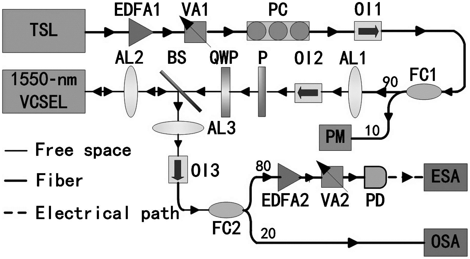
Figure 1 shows the schematic of the experimental setup. The output of a tunable semiconductor laser source (Ando AQ4321A) first passes through an erbium-doped fiber amplifier (EDFA1, Corning PureGain 2500C), a variable attenuator (VA1), a polarization controller (PC), an optical isolator (OI1), and then is split into two parts by a 10/90 fiber coupler (FC1). One part is connected to a power meter (PM) to monitor the injected power . The other is transformed into circular polarization light via an aspheric lens (AL1), OI2, a polarizer (P), and a quarter-wave plate (QWP) whose optical axis is positioned at 45° relative to the transmission axis of the polarizer. The polarization characteristics of the output from the QWP can be determined through sending it to another polarizer named as an analyzer. Rotating continuously the analyzer and detecting the transmitted power from the analyzer, the output from the QWP can be judged as circular polarization light once the detecting power keeps a constant. Then, such circular polarization light is sent to a commercial 1550 nm VCSEL (Raycan) via a beam splitter (BS) and AL2. The output of the 1550 nm VCSEL passes through AL2, BS, AL3, OI3, and FC2, and then is sent to a detection system. The detection system consists of an optical spectrum analyzer (OSA, Ando AQ6317C) with a wavelength resolution of around 0.01 nm, a 12 GHz bandwidth photodetector (PD, New Focus 1544-B) and an electrical spectrum analyzer (ESA, Agilent E4407B, 26.5 GHz bandwidth). During the whole experiment, the temperature and current of the 1550 nm VCSEL are controlled by a laser driver (ILX-Lightwave LDC-3724B), and the temperature of the 1550 nm VCSEL is stabilized at 16.14°C.

Figure 1.Experimental setup. TSL: tunable semiconductor laser; 1550 nm VCSEL: EDFA: erbium-doped fiber amplifier.
Figure 2(a) gives the polarization-resolved curve for a solitary 1550 nm VCSEL, and the threshold current of the laser is approximately 1.70 mA. For , the polarization component () with a shorter wavelength oscillates and polarization component () with a longer wavelength is suppressed completely, and then the solitary VCSEL operates at polarization mode ( mode). When the bias current is increased from 7.10 to 7.50 mA, the is excited and both two PCs coexist. For , the becomes the dominant PC and the power ratio between two PCs is larger than 30 dB, which means that type I PS (from the higher-frequency PC to the lower-frequency PC) happens. For , the oscillates and the is suppressed completely, and then the solitary VCSEL operates at polarization mode ( mode). Figures 2(b), 2(c), and 2(d) display the optical spectra of the solitary 1550 nm VCSEL biased at 4.00, 7.40, and 7.60 mA, respectively. From Fig. 2(c), it can be seen that, for , two PCs are coexisted and the wavelength offset between two PCs is about 0.356 nm. As shown in Figs. 2(b) and 2(d), the solitary 1550 nm VCSEL operates at a mode under and an mode under , respectively. Next, we will discuss the PS characteristics of a 1550 nm VCSEL subject to CPOI under two cases. One case is that the solitary 1550 nm VCSEL operates at mode, and the other is the case that the solitary 1550 nm VCSEL operates at mode.
Figure 2.(a) Polarization-resolved curve and optical spectra for a solitary 1550 nm VCSEL biased at (b) 4.00, (c) 7.40, and (d) 7.60 mA, respectively.
Here, we take the case of as an example. As shown in Fig. 2(b), under this current the solitary 1550 nm VCSEL operates at mode. After introducing CPOI with the frequency detuning (, where and are frequencies of the injected light and of the solitary 1550 nm VCSEL, respectively) fixed at 5.65 GHz, the dependence of polarization-resolved output power of the 1550 nm VCSEL subject to CPOI on injected power is presented in Fig. 3. From this diagram, it can be seen that, for a relatively small injected power , the remains as the dominant role. However, when the injected power exceeds 0.200 mW, the output power of the will be larger than that of the , and therefore the becomes the dominant component. Continuously increasing to 0.240 mW, the power decreases suddenly to a low level; meanwhile the power reaches a high level, i.e., type I PS occurs. It should be pointed out that the actual power ratio between the and the after occurring PS should be larger than that presented in this diagram since the recorded optical power of includes part of injected light that is reflected by the facet of the 1550 nm VCSEL.
Figure 3.Polarization-resolved power versus injected power under and , where the solid line and dash line with dot represent the and , respectively.
The above results show that, through introducing CPOI, a gradual PS can be achieved. Furthermore, the dynamical state of total outputs of the 1550 nm VCSEL may be changed due to CPOI. The evolution of nonlinear dynamical behaviors with the injected power is shown in Fig. 4 under , where the left column denotes optical spectra centered at the frequency of the , and the right column denotes the corresponding radio frequency (RF) spectra. As shown in Fig. 4(a), without CPOI (), the dominant PC is and the is suppressed completely, and a flat RF spectrum without a pronounced peak can be observed, which illustrates that the laser operates at a stable state (S). Under [as shown in Fig. 4(b)], two PCs co-existed, and only a frequency peak located at 2.90 GHz can be observed in the corresponding RF spectrum, which denotes two PCs operating at period one (P1) state. For [as shown in Fig. 4(c)], the oscillates and the is suppressed, and the fundamental frequency with 3.30 GHz and its subharmonic with 1.68 GHz can be observed in the corresponding RF spectrum. As a result, the laser operates at period-two (P2) oscillation. Further increasing to 0.115 mW [as shown in Fig. 4(d)], the still plays a dominant role and the is suppressed, and the laser operates at P1 oscillation with the fundamental frequency of 3.97 GHz. For [as shown in Fig. 4(e)], the peak of the optical spectrum is stably locked at , and a flat RF spectrum has been observed, which illustrates that the laser operates at the stable injection locking (SIL) state.
Figure 4.Optical spectra (left column) centered at and the corresponding RF spectra (right column) for the total power of the 1550 nm VCSEL biased at 4.00 mA subject to CPOI with and different injected powers. The injected powers in (a)–(e) are 0, 0.019, 0.059, 0.115, and 1.250 mW, respectively.
Figure 5 presents a mapping of the dynamical states of the total outputs of 1550 nm VCSEL in the parameter space of and under , where P1 & PS I, P2 & PS I and SIL & PS I denote type I PS accompanying P1 oscillation, P2 oscillation, and SIL, respectively, and the white region represents the case without PS. From this diagram, it can be observed that, under suitable injection strength and frequency detuning, type I PS can happen and the PS always accompanies P1, P2, or SIL. Additionally, the minimal value of the injected power required for type I PS for different can also been obtained. As shown in this diagram, displays an asymmetric behavior with , and a negative value of is more helpful for obtaining a smaller due to the redshift induced by optical injection. For , the injected power required for PS achieves its minimal value 0.008 mW.
Figure 5.Mapping of the dynamical behaviors of the 1550 nm VCSEL subject to CPOI in the parameter space of and under . P1 & PS I, P2 & PS I, and SIL & PS I represent type I PS accompanying with P1 oscillation, P2 oscillation, and SIL, respectively, and the white region (marked with “others”) represents the region without PS.
Next, we take the case of as an example to discuss PS characteristics induced by CPOI in the 1550 nm VCSEL, which operates at mode under free running. Considering the plays a dominant role while the is suppressed, under this case the frequency detuning is defined as , where and are frequencies of the injected light and the of the solitary 1550 nm VCSEL, respectively. Fig. 6 shows the dependence of the polarization-resolved output power on of CPOI under . From this diagram, it can be seen that, for a relatively small injected power , the plays a dominant role. When the injected power exceeds 0.300 mW, the power suddenly increases and then the becomes the dominant component; meanwhile the power of the decreases to a low level, which indicates that type II PS (from lower frequency PC to higher frequency PC) happens gradually. Similar to the case in Fig. 3, the reflected light from the facet of the 1550 nm VCSEL results in the decrease of the power ratio between the and after occurring type II PS.
Figure 6.Polarization-resolved power versus injected power under and , where the solid line and dash line with dot represent the and , respectively.
Figure 7 shows the evolution of nonlinear dynamical behaviors with the injected power under and . For the solitary 1550 nm VCSEL [as shown in Fig. 7(a)], the acts a dominant role while the is suppressed completely and a flat RF spectrum can be observed, which illustrates that the laser operates at stable state. When [as shown in Fig. 7(b)], the is suppressed and the plays the dominant role, and one frequency peak located at 4.71 GHz can be observed, which illustrates that type II PS happens while the laser operates at P1 oscillation. When is increased to 0.108 mW [as shown in Fig. 7(c)], only the can be observed in the optical spectrum, and a 5.59 GHz fundamental frequency and a 2.76 GHz subharmonic frequency can be observed in the corresponding RF spectrum, which denotes the laser operates at P2 oscillation. Further increasing to 0.680 mW [as shown in Fig. 7(d)], the laser operates at P1 oscillation whose fundamental frequency is increased to 8.55 GHz.
Figure 7.Optical spectra (left column) centered at and the corresponding RF spectra (right column) of the total power of the 1550 nm VCSEL biased at 7.60 mA subject to CPOI under and different injected powers. The injected powers in (a)–(d) are 0, 0.040, 0.108, and 0.680 mW, respectively.
Figure 8 presents a mapping of the dynamical behaviors of the total output of the 1550 nm VCSEL in the parameter space of and for . From this diagram, it can be seen that under suitable injection strength and frequency detuning type II PS can be observed. Similarly, type II PS always accompanies, P1 oscillation, P2 oscillation, or SIL. In addition, the minimal injected power required for type II PS for different can also been observed. The minimal value of injected power required for PS is 0.004 mW for and there is a shape “S” with a window appearing centered at for . Moreover, for positive frequency detuning, with the increase of the detuning frequency, the minimal injected power first increases to a maximum, then decreases to a minimum, and finally increases gradually.
Figure 8.Mapping of the dynamical behaviors of the 1550 nm VCSEL subject to CPOI in the parameters space of and under . P1 & PS II, P2 & PS II, and SIL & PS II denote type II PS accompanying with P1 oscillation, P2 oscillation and SIL, respectively;the white region (marked with “others”) denotes without PS.
By the way, compared with the pioneering work by Al-Seyab et al.[18], where a mapping of the dynamical behaviors of a 1550 nm VCSEL subject to orthogonal optical injection was presented and the PS accompanying P1 or SIL was observed, we have additionally observed the PS accompanying P2 in a 1550 nm VCSEL subject to CPOI.
In conclusion, the PS characteristics in a 1550 nm VCSEL subject to CPOI are experimentally investigated. The results show that, under different biased current, the solitary 1550 nm VCSEL can operate at mode with a shorter wavelength, two PCs coexisted, or mode with a longer wavelength. For the case that the solitary 1550 nm VCSEL operates at mode, type I PS (from higher-frequency PC to lower-frequency PC) can be observed after introducing CPOI with a proper injected power and detuning frequency between the injected light and the mode of the solitary VCSEL, and the curve of the minimal injected power required for type I PS versus exhibits a minimum locating at the negative frequency detuning region. For the solitary 1550 nm VCSEL operating at mode, type II PS (from lower-frequency PC to higher-frequency PC) can also be observed via CPOI under suitable injected power and detuning frequency between the injected light and the mode of the solitary VCSEL, and the curve of required for type II PS versus exhibits two minima. In additiona, mappings of the nonlinear dynamical states of 1550 nm VCSEL subject to CPOI have been given in parameters space of the injected power and frequency detuning. This work is expected to be helpful in comprehending the PS characteristics and its applications of 1550 nm VCSELs subject to CPOI.
References
[1] H. Kawaguchi. Bistabilities and Nonlinearities in Laser Diodes(1994).
[2] S.-L. Yan. Chin. Opt. Lett., 13, 040401(2015).
[3] L. Yang, W. Pan, L. Yan, B. Luo, P. Mu, N. Li. Chin. Opt. Lett., 13, 041403(2015).
[4] B. Farias, T. Passerat de Silans, M. Chevrollier, M. Oriá. Phys. Rev. Lett., 94, 173902(2005).
[5] C. Masoller, T. Sorrentino, M. Chevrollier, M. Oria. IEEE J. Quantum Electron., 43, 261(2007).
[6] G.-Q. Xia, S.-C. Chan, J.-M. Liu. Opt. Express, 15, 572(2007).
[7] Z. Rao, S. Vo, J. S. Harris. Chin. Opt. Lett., 6, 748(2008).
[8] R. Michalzik. VCSELs: Fundamentals, Technology and Applications of Vertical-Cavity Surface-Emitting Lasers(2013).
[9] W.-L. Zhang, W. Pan, B. Luo, X.-F. Li, X.-H. Zou, M.-Y. Wang. Chin. Phys., 16, 1996(2007).
[10] X.-B. Huang, G.-Q. Xia, Z.-M. Wu. Acta Phys. Sin., 59, 3066(2010).
[11] C. Masoller, M. S. Torre, P. Mandel. J. Appl. Phys., 99, 026108(2006).
[12] B. Pyvkin, K. Panajotov, A. Georgievski, J. Danckaert, M. Peeters, G. Verschaffelt, H. Thienpont, I. Veretennicoff. J. Opt. Soc. Am. B, 16, 2106(1999).
[13] G. Verschaffelt, J. Albert, I. Veretennicoff, J. Danckaert, S. Barbay, G. Giacomelli, F. Marin. Appl. Phys. Lett., 80, 2248(2002).
[14] Y. Hong, R. Ju, P. S. Spencer, K. A. Shore. IEEE J. Quantum Electron., 41, 619(2005).
[15] J. Paul, C. Masoller, Y. Hong, P. S. Spencer, K. A. Shore. J. Opt. Soc. Am. B, 24, 1987(2007).
[16] T. Deng, Z.-M. Wu, Y.-Y. Xie, J.-G. Wu, X. Tang, L. Fan, K. Panajotov, G.-Q. Xia. Appl. Opt., 52, 3833(2013).
[17] A. A. Qader, Y. Hong, K. A. Shore. IEEE J. Lightwave Technol., 29, 3804(2011).
[18] R. Al-Seyab, K. Schires, N. Ali Khan, A. Hurtado, I. D. Henning, M. J. Adams. IEEE J. Sel. Top. Quantum Electron., 17, 1242(2011).
[19] M. Sciamanna, K. Panajotov. Phys. Rev. A, 73, 023811(2006).
[20] A. Hurtado, I. D. Henning, M. J. Adams. IEEE Photon. Technol. Lett., 21, 1084(2009).
[21] Z. G. Pan, S. Jiang, M. Dagenais, R. A. Morgan, K. Kojima, M. T. Asom, R. E. Leibenguth, G. D. Guth, M. W. Focht. Appl. Phys. Lett., 63, 2999(1993).
[22] I. Gatare, J. Buesa, H. Thienpont, K. Panajotov, M. Sciamanna. Opt. Quantum Electron., 38, 429(2006).
[23] M. Torre, A. Hurtado, A. Quirce, A. Valle, L. Pesquera, M. Adams. IEEE J. Quantum Electron., 47, 92(2011).
[24] A. Quirce, P. Pérez, H. Lin, A. Valle, L. Pesquera, K. Panajotov, H. Thienpont. IEEE J. Quantum Electron., 50, 921(2014).
[25] R. Al-Seyab, K. Schires, A. Hurtado, I. D. Henning, M. J. Adams. IEEE J. Sel. Top. Quantum Electron., 19, 1700512(2013).
[26] F. Koyama. Chin. Opt. Lett., 6, 755(2008).
[27] S. S. Alharthi, A. Hurtado, V. H. Korpijarvi, M. Guina, I. D. Henning, M. J. Adams. Appl. Phys. Lett., 106, 021117(2015).