

Peiyan Wu, Yongjiang Xu, Yanhao Lin. A novel rapid cooling assembly design in a high-pressure cubic press apparatus[J]. Matter and Radiation at Extremes, 2024, 9(2): 027402
- Matter and Radiation at Extremes
- Vol. 9, Issue 2, 027402 (2024)
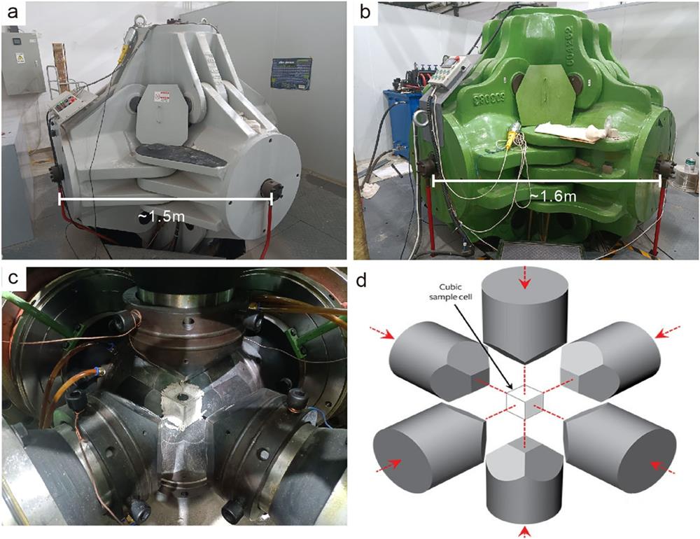
Fig. 1. (a) and (b) Photographs of the GY420 and GY560 cubic presses, respectively, at the HPSTAR high-pressure laboratory. (c) Photograph of six tungsten carbide (WC) anvils and a compressed cube from the GY560 cubic press. (d) Sketch of the pressurizing system of the cubic press. The six WC anvils are driven by a computer-controlled hydraulic system to generate isotropic static high pressure in the central cube from three dimensions.
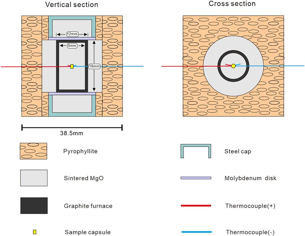
Fig. 2. Traditional assembly for cubic press shown in vertical and cross sections. The cube edge length is 38.5 mm.
Fig. 3. Newly developed rapid cooling assembly shown in vertical section (a), cross section (b), and 3D model (c). For the key, see Fig. 2 . A slim graphite rod (2.5 mm in diameter) is placed vertically in the center of the assembly, and sample capsules are inserted into this rod. In addition, two sample capsules can be used at the same time, symmetrically set on either side of the thermocouple junction in the center of the assembly. The cube edge length is 38.5 mm.
Fig. 4. Comparison of cooling paths between the rapid cooling assembly and the conventional assembly, after experiments at a pressure of 5 GPa and temperatures of 1800–1900 °C. The starting time of the cooling is placed at the time of the last high-temperature reading, and so the corresponding quench rates are minimum values. Previously reported cooling rate profiles7 of a piston cylinder (PC) and a multi-anvil assembly are also shown.
Fig. 5. Relation between power and temperature for the conventional and rapid cooling assemblies, demonstrating the higher nominal heating efficiency of the rapid cooling assembly.
Fig. 6. Backscattered electron (BSE) images [(a) and (b)] and EPMA-derived chemical composition line analyses [(c) and (d)] of experiments performed at the same temperature and pressure and identical starting materials with the conventional assembly [(a) and (c)] and rapid cooling assembly [(b) and (d)]. Bright areas are S-rich iron metal; gray areas are silicate glass (light grey) and quench minerals with interstitial silicate glass [dark grey in (a)]. Sf, iron sulfide; Q.C, quenched crystal; I.Gl, interstitial glass; Gl, glass.
|
Table 1. Electron microprobe analyses of the chemical compositions of multicomponent silicate glass with and without quenchable texture taken along a profile line through the section and polished run products.

Set citation alerts for the article
Please enter your email address
© Copyright 2018-2021 | Chinese Laser Press. All Rights Reserved 沪ICP备15018463号-20