Cavity-coupled plasmonic structure is demonstrated to be a simple and effective tool to manipulatelight, enhance the biosensing figure of merit, and control the polarization state. In this Letter, we demonstrate the tunability of the chiroptical effect of cavity-coupled chiral structure, i.e., sandwich chiral metamaterials (SCMs), in whichradiation coupling dominates the interaction between particles. Two types of SCMs whose building blocks are 3D chiral and 2D chiral, respectively, are numerically studied. Distinct responses are observed in these two materials. The chiroptical effect can be effectively manipulated and enhanced in the 2D case, while the SCMs consisting of 3D chiral layers keep the chiroptical effecta constant. A theoretical analysis based on matrix optics is developed to explain the corresponding phenomena, which gives a reasonable agreement with numerical simulations.
The chiroptical effect, including circular dichroism (CD) and optical activity (OA), derives from higher-order effects. The largest contributions are from the electric dipole-magnetic dipole (dipolar) and electric dipole-electric quadrupole (quadrupolar) interactions. This chiroptical effect paves the way for the enantiomer biosensor[1,2] and manipulating the polarization states of light[3–5]. Recently, chiral metamaterials (CMMs) composed by electric or magnetic resonators have been demonstrated to be an effective tool to enhance the chiroptical effect. Typical chiroptical effects can be divided into two groups, 3D chirality and 2D chirality. 3D chirality widely exists in natural materials and can be found in artificial 3D CMM[3] and 2D CMM, which has high symmetry such as gammadions[6], crosses[6,7], and any metal particles arranged in fourfold rotational symmetry[6,8,9]. 3D chiral structures can result in OA and the associated phenomenon of CD. The corresponding matrix for the isotropic 3D-chiral medium is the diagonal matrix[10,11]. Planar CMMs are often 2D chiral types such as fish scale[10], split ring[12,13], ‘L’ particle[14], and so forth. Detections of circular conversion dichroism (CCD) took place for 2D-chiral metamolecules. The transmission matrix for a planar chiral medium is a nonHermitian matrix with equal diagonal elements. The similarity of 3D and 2D chirality is that they both have total transmission difference, while a difference in both the magnitudes and phase of the diagonal terms in the transmission matrix is linked to 3D chirality, and a difference in magnitudes of the off-diagonal terms is linked to 2D chirality. Due to the convenient processing technology, planar CMMs are often manufactured and sandwich chiral metamaterials (SCMs) are frequently utilized to enhance the chiroptical effect[6,7,9,13,15].
To date, most SCMs are arranged with a short vertical spacing. In this approach, the magnetic dipole can be easily excited and the corresponding electromagnetic response can be understood within the plasmon hybridization model[16]. However, the particle’s resonance is dominated by quasi-electrostatic forces for short vertical spacing. The radiative effect is neglected, and the influence of the Fabry–Perot (FP) cavity is dramatically suppressed. Based on the past research, the cavity-coupled plasmonic structure can be a simple and effective method to manipulate the light, enhance the biosensing figure of merit, and control the polarization state[17]. Particularly, FP resonance can enhance the spin Hall effect in layered nanostructures and the spin-dependent displacements for the CMMs can reach as high as several tens of wavelengths at certain incident angles[18,19]. Combining the above advantages, the SCM may provide a possible way to enhance the photonic spin Hall effect.
Additionally, active chiral plasmonics have attracted a considerable amount of interest due to their tunability of the chiroptical effect and the potential applications in highly integrated polarization sensitive devices[20]. Much new research about tailoring the electromagnetic response with FP cavity-coupled SCMs have been published in recent years[21–23], while the reports about tailoring the chirality are rare. Indeed, the transmission and reflection efficiencies of SCMs can be periodically manipulated by changing the cavity length, which can be understood by far-field coupling[16]. Thus, a natural expectation is that, by inducing the FPcavity mode into the SCM, we can tailor the chiroptical effect and enhance it.
Sign up for Chinese Optics Letters TOC. Get the latest issue of Chinese Optics Letters delivered right to you!Sign up now
In this Letter, we demonstrate the tunability of the SCM’s chiroptical effect in the far-field coupling region. Two types of SCMs that consist of metamaterials with 3D chirality and 2D chirality are numerically calculated. It is found that we can effectively manipulate and enhance the chiroptical effect by the SCM whose building block is 2D chiral. However, for the SCM consisting of 3D chiral media, only the transmitted intensity is periodically tailored, the chiroptical effect remains unchanged during the variation of spacer thickness. In the theoretical analysis, we explain the above phenomena from the view of matrix optics. Good agreement has been achieved between the theoretical analysis and numerical results.
The right circular polarization (RCP) and left circular polarization (LCP) in this Letter are the base vectors and denoted as ‘’ and ‘’. The transmission/reflection coefficients can be defined by , where ‘’ and ‘’ are the polarized states of output and incident light. The Jones matrix is used to characterize the materials and is defined as
The intensity and phase of the corresponding matrix components are denoted by , , , and .
According to the basic definition, the CD and OA can be calculated as
While the usual 2D chiral particle is anisotropic, the calculated formula of OA can not be applied. However, for linearly polarized incident light, the transmitted light’s azimuth angle can be calculated by the Stokes parameters. To do this, the linearly polarized light is incident along the horizontal orientation and the azimuth angle is calculated instead of OA, for the 2D chiral particles, where . Based on the standard finite-difference time domain (FDTD) method, we begin our analysis by using commercial software FDTD Solutions. The periodic boundary conditions are applied to the and directions and the perfect matching layer boundary to the direction.
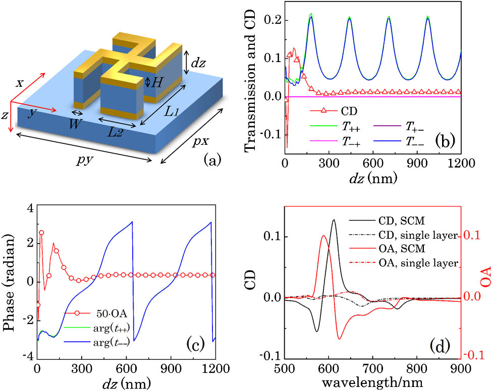
First, the 3D chiral structures, gammadions, are used to construct SCMs, as shown in Fig. 1(a). For one single chiral gammadion, the length of , , and are 50, 250, and 125 nm, respectively, and the thickness () is 50 nm. The lattice constant is . The middle layer between the top and bottom chiral media and the substrate are made by dielectric media SiO2 with a refractive index of 1.46. The thickness of the middle dielectric layer (, FP cavity length) is adjusted from 6 to 1200 nm to investigate the influence of the chiral FP cavity length in simulations. The material parameter of gold is chosen from the software database (Gold Johnson Christy).
Figure 1.Simulation results of an SCM consisting of 3D chiral particles. (a) Schematic of SCMs formed by the gammadion array. (b) Simulated transmission efficiencies and CD at a resonance wavelength of 612.7 nm. (c) The phase of , and OA as a function of at a wavelength of 612.7 nm. (d) The simulated CD and OA of the single- layer chiral media and the SCM with .
Figure 1(b) shows the transmission efficiencies and the CD spectra at a resonant wavelength of 612.7 nm as a function of . As is shown, when is larger than 100 nm, and periodically change with a period of 260 nm. 3D chirality is present from the difference between co-polarized components, and 2D chirality is absent due to the cross-polarized components being equal to zero. The polarization eigenstate is still circular polarization. Please note that the variations of and are synchronous when changes from 200 to 1200 nm, resulting in the CD curve remaining unchanged. Thus, we can hardly tune the CD by adjusting the cavity length. In the short spacing region (6 to 200 nm), the CD transforms rapidly; a large CD value is obtained at .
Similarly, OA changes quickly during the variation of from 6 to 200 nm and then remains the same from 200 to 1200 nm [Fig. 1(c)]. A maximum value of OA occurs at . Figure 1(d) shows the CD and OA spectra of a single gammadion layer and the SCM with . An obvious enhancement of the chiroptical signal is obtained from SCMs near the wavelength of 612.7 nm.
Figure 2 is the color map of CD, OA, , and as a function of wavelength and the cavity length . Large CD and OA values can be found when is smaller than 200 nm since, in the short region, the interaction is mediated by quasi-electrostatic forces between the particles. We clarify that this giant chirality is caused by the near-field coupling. Beyond this region, CD and OA remain constant while a periodic modulation effect due to an FP cavity is observed for and in the whole band. The transmittance efficiencies and are very similar. However, they are indeed different, but with just a small difference. The characteristic of the 3D chirality is shown, due to this small difference.
Figure 2.(a) Simulated CD, (b) OA, (c) , and (d) for the SCMs consisting of 3D chiral particles as a function of wavelength and cavity length.
From the figures, it can be seen that it is hard for the SCM to tailor the chiroptical effect as a function of cavity length if the SCMs are comprised of 3D chiral media. The giant chiroptical response is observed when the FP length is smaller than 200 nm, which is attributed to the near-field coupling effect. The property of an unchanged chiroptical effect will be explained later from the view of matrix optics.
The SCM formed by an “L” particle, which has definite 2D chirality, is studied as shown in Fig. 3(a). The width (), height (), length (), and short arms () of a single L-shape nanostructure are 80, 50, 240, and 120 nm, respectively. The lattice constants and are 340 and 220 nm, respectively.
Figure 3.Simulation results of the SCM consisting of 3D chiral particles. (a) A schematic of SCMs formed by the ‘L’ particle. (b) Simulated transmission efficiencies and CD at a wavelength of 677.2 nm. (c) The azimuth angle as a function of at a wavelength of 677.2 nm. (d) Simulated CD and of the singlelayer chiral media and the SCM with .
Figure 3(b) depicts the transmitted efficiencies and CD spectra at a resonance wavelength of 677.2 nm. Compared with the last case, the CD curve shows a dramatic difference in the far-field coupling region. In another words, the CD changes periodically during the variation of from 150 to 1200 nm, indicating that this SCM type can tailor the CD periodically like tailoring the transmission efficiencies. A large CD value of about 0.64 is also obtained at a large cavity length (110, 370, 680, and 980 nm) and repeats at a period about 300 nm. Additionally, the variations of transmitted efficiencies are still periodic, but not synchronous. Both 2D chirality and 3D chirality are observed due to and . Similarly, the azimuth angle exhibits a period change in the far-field coupling region in Fig. 3(c). Thus, the SCM of this type can tailor not only the CD but also at a remarkable level.
Comparing with the single-layer building block [Fig. 3(d)], the CD of the SCM with is dramatically enhanced by 3.5 times. is also enhanced, as shown. This shows that the SCM can obtain a huge chiroptical effect not only in the short vertical spacing, but also at a very large spacing if the building block has 2D chirality. A much stronger SCM chiroptical effect can be realized by further design of the shape features.
Figure 4 contains the color maps of CD, azimuth angle , transmission efficiencies as a function of wavelength, and the cavity length. In Fig. 4(a) we can observe a periodic modulation of CD at a resonance wavelength 677.2 nm (marked by the white dash line). The maximum CD value at , 370, 680, and 980 nm are nearly the same.
Figure 4.(a) Simulated CD, (b) azimuth angle , (c) , (d) , (e), and (f) for the SCMs consisting of ‘L’ chiral particles as a function of wavelength and cavity length.
Figure 4(b) shows a periodic variation for the azimuth angle . The change of transmission efficiencies is still periodic in Fig. 4(c)–4(f), and the difference between and , and and are more evident along the wavelength of 677.2 nm.
In a word, SCMs consisting of 2D chiral particles can effectively tailor the CD and OA spectrum in the large cavity distance. The corresponding chiroptical effect is also enhanced, indicating that a new route to control the chiroptical effect is open. Next, we will theoretically analyze the above chiral behavior from the view of matrix optics.
In the far-field coupling region, each layer of CMM arrays can be regarded as a single layer of media and the behavior of the SCM can be understood by multiple reflections in the cavity, as shown in Fig. 5(a). Matrix optics is used here to decide the Jones matrix of the SCM.
Figure 5.Theory model of SCM and analytic fitting curves. (a) Schematics of the transmission of the SCM. Analytic fitting curves of (b) CD and (c) OA for the SCM consisting of gammadion arrays at a wavelength of 612.7 nm. Analytic fitting curves of (d) CD and (c) azimuth angle for the SCM consisting of “L” particle arrays at a wavelength of 677.2 nm.
To simplify the discussions, we consider the first two transmitted lights to decide the transmitted lights where is the distance between the chiral media 1 and 2, , is the wave vector in the vacuum, is the effective index of the middle layer between the media 1 and 2, is the cavity length, and ‘’ and ‘’ denote the forward and backward propagation directions. The influence of the substrate and middle spacer is neglected, thus media 1 is identical with media 2. Once the reflection and transmission properties of single chiral media are known, we can predict the SCM’s chiral property (CD, OA) from the analytic Eq. (4).
For the chiral media that has 3D chirality, a single media’s matrix can be expressed as
The form of is different from but has the same meaning of 3D chirality[24,25]. As is known, the definition of circularly polarized light is reversed after being reflected. Thus, the co/cross-polarization light in transmission turns into cross/co-polarization light in reflection. For the 3D chirality, the off-diagonal elements in the transmission matrix are zero. Thus, in reflection, the diagonal elements should also be zero.
Additionally, we know that the reflection coefficient of the 3D chiral media is the same for the LCP and RCP[26,27], i.e., . Thus, we have
Substituting Eqs. (5) and (6) into Eq. (4), the expression of SCM’s Jones matrix and the corresponding CD and OA are
The theory-deduced equations agree with the simulation results and show that the SCM is still 3D chiral, the change of co-polarization coefficients is synchronous, and the resulting CD and OA are constant during the variation of . Thus, in this case, the chiroptical effect is always unchanged, no matter how far the two CMM layers are separated, and mainly depends on the property of the single media.
For the single 2D chiral media, each element in the transmission and reflection matrix is nonzero, leading the final formula to be complex and long. Corresponding analysis should take all elements’ influence into consideration, although it is still hard to simplify the formula and get a general conclusion. However, as Eq. (4) is known, we can quantitatively study the behavior of the SCM. We extract the simulated transmission/reflection coefficients of the single layer and substitute these data at the resonance wavelength into the SCM’s analytic model, Eq. (4). The fitting curves about the gammadion and “L” particle array are plotted in Figs. 5(b)–5(e). As is shown, for the SCM whose building blocks are 3D chiral, the analytic formula predicts that its CD value remains unchanged during variation of the cavity length. Theory-predicted OA is also plotted in Fig. 5(c), which is a constant, while for the SCM consisting of 2D chiral particles the response versus periodicity remains the same, and the magnitude of the fitting transmission efficiencies and the CD are similar to the simulation results. Both 2D and 3D chirality are also observed. Compared with simulation results, the fitted azimuth angle is shifted up, but the response versus periodicity is similar. Thus, the simulated chiroptical effect can be interpreted from the matrix optics.
The analytic model presented here has a good prediction of the chiral behavior of the SCM, which has a similar change tendency with the simulated results. The misfit may be attributed to the ignorance of the high-order transmitted wave and the accuracy of the extracted data. Except for this, Eq. (4) is general and valid for the SCM whose bottom and top layers are identical.
In conclusion, we demonstrate a new method to tune the chiroptical effect by coupling the FP cavity with the SCM. Two types of SCM are studied. Particularly, the SCM consisting of a 2D chiral particle can effectively tailor the enhanced chiroptical effect by adjusting the cavity length, while the SCM whose building block is 3D chiral keeps the chiroptical effect unchanged. Matrix optics is developed and the corresponding fitting curves have a reasonable agreement with the simulation results. Our study has not only shed new light on the understanding of the chiroptical effect in SCMs, but also has provided a unique pathway toward broad applications.