1School of Optoelectronics, Beijing Institute of Technology, Beijing 100081, China
2Key Laboratory of Photo-electronic Imaging Technology and System (Beijing Institute of Technology), Ministry of Education of China, Beijing 100081, China
Visible light positioning becomes popular recently. However, its performance is degraded by the indoor diffuse optical channel. An artificial neural-network-based visible light positioning algorithm is proposed in this Letter, and a trained neural network is used to achieve positioning with a diffuse channel. Simulations are made to evaluate the proposed positioning algorithm. Results show that the average positioning error is reduced about 13 times, and the positioning time is reduced about two magnitudes. Moreover, the proposed algorithm is robust with a different field-of-view of the receiver and the reflectivity of the wall, which is suitable for various positioning applications.
With increasing applications related to location-based services (LBS) and growing indoor localization requirements of mobile devices, such as robots and mobile phones, indoor positioning becomes a promising research area. Due to the high attenuation and multi-path effect, the widely used global positioning system (GPS) fails in the indoor circumstance. To remedy this problem, many indoor localization techniques based on radio frequency identification (RFID), ultra-wideband (UWB), wireless local area network (WLAN), infra radiation (IR), and Bluetooth have been proposed[1]. Unfortunately, these techniques have limitations on accuracy or in high-cost infrastructures. Recently, visible light communication (VLC) based on light-emitting diodes (LEDs) has gained more and more attention[2]. It has several advantages, such as a high-bandwidth, low-cost, no electromagnetic interference (EMI), high security, the reuse of an indoor lighting infrastructure, and it has the potential to achieve indoor visible light positioning[3].
Similar to VLC, visible light positioning also takes advantage of an existing indoor lighting infrastructure and is more precise than traditional indoor positioning methods[4]. According to the kind of detector at the receiver, indoor visible light positioning methods can be divided into two categories, namely photodiode (PD) based and image-sensor-based[5–9]. To consider the tradeoff between both accuracy and system complexity, PD is used as the detector in most visible light positioning systems. A PD-based visible light positioning system, which combined with the received signal strength (RSS) based positioning algorithm and radio frequency allocation technique, has been suggested in Ref. [5], and the average error of a corresponding experimental system is 2.4 cm. In Ref. [6], the basic framed slotted ALOHA technique has been combined with the typical RSS-based positioning algorithm, and an accuracy of 5.9 cm with 95% confidence is achieved. In this typical visible light positioning research, the RSS is used to estimate the distances between the receiver and different transmitters, then the localization information is extracted accordingly. In these investigations, only the line-of-sight (LOS) optical channel is considered. Unfortunately, in actual usage, the RSS will also be influenced by the diffuse optical channel, and that will degrade the performance of a specific visible light positioning system[10,11]. The impact of a diffuse optical channel on a visible light positioning system is investigated in Ref. [12], and the calibration approaches, such as select stronger LED signals and shortening the distances between LEDs, have been proposed to decrease the performance degradation. In other research, the orthogonal frequency division multiplexing (OFDM) technique has been applied to mitigate the distortion of the diffuse optical channel, and the root mean square (RMS) error of the whole positioning scenario can be reduced about four times[13].
In this Letter, a visible light positioning algorithm based on the RSS and artificial neural network training is proposed to achieve highly precise and efficient indoor visible light positioning in scenarios with a diffuse optical channel. A typical back propagation (BP) artificial neural network is trained first with the RSS of several sampled points on the receiving plane, and then the trained artificial neural network is used to extract the position information of the receiver according to the RSS. Simulations are made to evaluate the performance and robustness of the proposed positioning algorithm. The results show that the average positioning error can be reduced about one magnitude, and the positioning time can be reduced about two magnitudes.
Sign up for Chinese Optics Letters TOC. Get the latest issue of Chinese Optics Letters delivered right to you!Sign up now
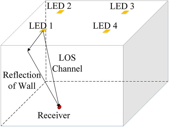
In this research, LEDs are used as the transmitter to perform the lighting, and the RSS from different LEDs are used to achieve indoor localization. We assume there is an indoor scenario with four walls and four LEDs, as Fig. 1 shows, and make it an example. Without the loss of generality, the diffuse optical channel with a onetime reflection of the wall is considered in this research[14], and the received optical power from a specific LED can be expressed as where and are the received optical power and transmitted optical power, respectively. is the channel direct current (DC) gain of the LOS channel, and is the DC gain of the diffuse optical channel.
Figure 1.Typical scenario of indoor visible light positioning.
The geometry of the diffuse optical channel can be shown as Fig. 2. For the LOS channel, the channel DC gain is given as[14]where is the physical area of the detector in a PD, denotes the Lambertian mode number according to the semi-angle at half-power of the LED. is the distance between the LED and receiver is the angle of incidence, is the angle of irradiance, and is the field-of-view (FOV) of the receiver. is the transmission gain of the receiver, and is the gain of the optical concentrator at the receiver, which can be expressed as where is the refractive index of the optical concentrator.
Besides the LOS channel, the reflection of the wall is also considered in this research. Without the loss of generality, we assume the walls are composed of many diffuse reflectors with area and reflectivity . Thus, the channel DC gain of the diffuse channel can be described by where and are distances, and are angles of incidence, and and are angles of irradiance.
Thus, with the channel DC gain of the LOS transmission and reflection of the wall, the electronic power of the received signal can be described as where is the responsivity of receiver, and is the variance of noise. To consider in a typical visible light positioning system, LEDs are modulated to transport signals, and time division multiplexing (TDM) methods or frequency division multiplexing (FDM) methods are used to achieve multiple access of different LEDs[15]. Thus, the inter-symbol interference (ISI) can be avoided, and the background noise can be filtered out. The variance of noise can be expressed as where , , and are an electronic charge, equivalent noise bandwidth, and Boltzmann’s constant, respectively. , , and denote the absolute temperature, the open-loop voltage gain, and the fixed capacitance of the PD. and represent the field effect transistor (FET) channel noise factor and the FET transconductance. and are constants equal to 0.562 and 0.0868, respectively.
The artificial neural network is a promising technology that can extract information from numerous data and has been used in outdoor localization systems based on the Global System for Mobile (GSM) communications[16,17]. In this Letter, to improve the performance of the RSS-based visible light positioning system with a diffuse optical channel, an algorithm that combines a typical BP artificial neural network and the RSS is proposed to achieve visible light positioning. The structure of the artificial neural network is shown in Fig. 3. The neural network can be divided into the input layer, the hidden layer, and the output layer. The inputs of the neural network are the RSS from different LEDs. On the other hand, the outputs are the coordinates of the receiver, and there are nodes in the hidden layer.
Figure 3.Structure of an artificial neural network.
The principle of the BP artificial neural network can be divided into two stages, namely the training stage and the trained stage. In the training stage, several sets of inputs and outputs are used, and the object of the training is to minimize the sum of the squared errors between the actual and the desired output values. After the training, with any meaningful inputs to the trained artificial neural network, corresponding outputs can be obtained. The block diagram of the proposed visible light positioning algorithm is shown in Fig. 4, and it can be divided into training steps and positioning steps. In the training steps, the scenario is first modeled with a diffuse optical channel. Several points on the receiver plane are sampled evenly, and the RSS from different LEDs is calculated at these points. Then, the RSS and coordinates of these points are treated as inputs and outputs, respectively, and used to train the artificial neural network until the sum of the squared error of these sampled points is minimized. In actual usage, considering the training steps are not executed frequently, a control center can be used to perform these steps, and update the neural network when the indoor scenario changes and the positioning error level increases. After the neural network is trained, it can be used to achieve indoor positioning. In the positioning steps, the light signal from different LEDs and additive noise captured by the receiver are processed by the trained neural network. Then, the coordinates of the receiver are obtained, namely the position of receiver is obtained.
Figure 4.Block diagram of the proposed visible light positioning algorithm.
Considering some key parameters of the diffuse optical channel (such as the reflectivity of the wall) cannot be set and adjusted accurately in actual scenarios, we have made many relevant simulations to evaluate the performance of the proposed visible light positioning algorithm, as in Refs. [10–13]. In the simulation, a typical indoor scenario, i.e., a four wall empty room, is investigated. There are four LEDs mounted downward vertically on the ceiling with the coordinates (, , 3), (, 1.5, 3), (1.5, , 3), and (1.5, 1.5, 3), and the coordinates of the center of the floor are (0, 0, 0). The receiver is placed upward vertically, and its vertical distance to ceiling is 3 m. Training points are sampled on the receiver plane, and its density is , and the other key parameters used in the simulation are listed in Table 1.
The two-dimensional distribution of the positioning error at the sampled points with a typical RSS-based positioning algorithm[11] is shown in Fig. 5(a), and the corresponding positioning error of the proposed artificial neural-network-based positioning algorithm is shown in Fig. 5(b). The results indicate that the typical RSS-based visible light positioning algorithm is strongly influenced by the diffuse optical channel, and the average error is 87.11 cm. On the contrary, with the proposed positioning algorithm, the positioning error at the trained points can be reduced effectively. With the proposed positioning algorithm, the average error at the sampled points is 6.39 cm, which is reduced about 13.6 times.
Figure 5.Positioning error at sampled points of (a) typical RSS-based positioning algorithm and (b) proposed neural-network-based positioning algorithm.
To evaluate the effectiveness of the proposed visible light positioning algorithm, its performance is simulated with 63001 points evenly placed on the receiver plane with a grid of , and the results are shown in Fig. 6(a). It can be found that besides the sampled points, which are used in the training steps, the trained artificial neural network is still working for other points on the receiver plane, and the average positioning error is 6.59 cm, which is reduced about 13.2 times when compared with the typical RSS-based positioning algorithm. Figure 6(b) shows the cumulative distribution function (CDF) of the positioning error. The results show that compared with the typical RSS-based algorithm, the proposed positioning algorithm is more accurate. The positioning error of 80% of the CDF of the proposed algorithm is about 10 cm, while the positioning error of 80% of the CDF of the typical RSS-based positioning algorithm is more than 160 cm. Moreover, the CDF curves of the 2601 sampled points and the 63001 test points is nearly same, which also verifies the effectiveness of the proposed artificial neural-network-based visible light positioning algorithm.
Figure 6.(a) Distribution of the positioning error on the receiver plane and (b) CDF of the positioning error with different times of iteration.
Generally, the performance of a BP artificial neural network is influenced by the number of hidden nodes. In Fig. 7, the average positioning error, RMS error, and P95 error (the error of 95% confidence) of a different number of hidden nodes is shown (zero nodes stands for the typical RSS-based positioning algorithm). It can be concluded that the proposed algorithm can improve the positioning performance greatly, and 20 hidden nodes is enough to achieve highly precise localization. On the other hand, to evaluate the efficiency of the proposed positioning algorithm, the training time and positioning time is counted in the simulations by a laptop. The average training time (of 10 times of training) and average positioning time (of 10 times of positioning for the 63001 points) with a different number of hidden nodes are shown in Table 2. The results indicate that with an increasing number of hidden nodes, the training time will increase accordingly. At the same time, after the training steps, the positioning time of the proposed artificial neural-network-based positioning algorithm is almost not influenced by the number of hidden nodes, and it is less than the typical RSS-based positioning algorithm by about two magnitudes. Thus, 20 hidden nodes are more suitable for the proposed scenario with a diffuse optical channel. In summary, the proposed artificial neural-network-based positioning method is more time-efficient and suitable for indoor localization applications, which is aiming for moving objects.
Figure 7.Positioning error with a different number of hidden nodes.
To evaluate the robustness of the proposed artificial neural-network-based positioning algorithm, simulations are made with 63001 evenly placed points on the receiver plane with different reflectivities of the wall and FOVs of the receiver. In Fig. 8, the performance of the proposed positioning algorithm is evaluated with various reflectivities of the wall, and other system parameters are still unchanged, as Table 1 shows. It indicates that with increasing reflectivity of the wall, the diffuse signal will become stronger, and the positioning performance of the typical RSS-based positioning method will become worse. On the contrary, the proposed artificial neural-network-based positioning method can still reduce the positioning error significantly and is not sensitive to the reflectivity of the wall. The performance of the proposed positioning algorithm with various FOVs of the receiver is shown in Fig. 9. It indicates that if a receiver with a larger FOV is used, the positioning error of the typical RSS-based positioning method will increase because more diffuse light will be captured. At the same time, the proposed neural-network-based positioning method can also reduce the positioning error by about a magnitude, and the positioning performance is nearly same for receivers with different FOVs. In all, the proposed artificial neural-network-based visible light positioning method can improve the positioning performance significantly and is effective with different scenarios and receivers.
Figure 8.Positioning error with a different reflectivity of the wall.
In this Letter, a visible light positioning algorithm combined with the RSS and a BP artificial neural network is proposed to achieve indoor visible light positioning in scenarios with a diffuse optical channel. The principle of the proposed positioning algorithm is analyzed, and then simulations are made to verify its accuracy, efficiency, effectiveness, and robustness. The results show that in a typical scenario with a diffuse optical channel, the average positioning error of the proposed positioning algorithm is about 13 times less than the typical RSS-based positioning algorithm, and the trained artificial neural network is effective to all the points on the receiver plane, which outperforms other relevant methods (in Refs. [12,13], the corresponding improvements are about 1.2 times and 3.9 times, respectively). The positioning time of the proposed algorithm is less than the typical RSS-based positioning algorithm by about two magnitudes, which means it is more time-efficient and suitable for the positioning of moving objects. Moreover, the proposed positioning algorithm is not sensitive to the reflectivity of the wall and the FOV of the receiver. So, it is effective in various scenarios. In conclusion, the proposed artificial neural-network-based positioning algorithm has more accuracy, efficiency, and robustness than the typical RSS-based methods in scenarios with a diffuse optical channel, and it is suitable for different LBS in various scenarios.
References
[1] H. Liu, H. Darabi, P. Banerjee, J. Liu. IEEE Trans. Syst. Man Cybern. C: Appl. Rev., 37, 1067(2007).