Integrated optomechanical crystal (OMC) cavities provide a vital device prototype for highly efficient microwave to optical conversion in quantum information processing. In this work, we propose a novel heterogeneous OMC cavity consisting of a thin-film lithium niobate (TFLN) slab and chalcogenide (ChG) photonic crystal nanobeam coupled by a wavelength-scale mechanical waveguide. The optomechanical coupling rate of the heterogeneous OMC cavity is optimized up to 340 kHz at 1.1197 GHz. Combined with phononic band and power decomposition, 17.38% energy from the loaded RF power is converted into dominant fundamental horizontal shear mode (SH0) in the narrow LN mechanical waveguide. Based on this fraction, as a result, 3.51% power relative to the loaded RF energy is scattered into the fundamental longitudinal mode (L0) facing the TFLN-ChG heterogeneous waveguide. The acoustic breathing mode of the heterogeneous OMC is successfully excited under the driving of the propagating L0 mode in the heterogeneous waveguide, demonstrating the great potentials of the heterogeneous piezo-optomechanical transducer in high-performance photon–phonon interaction fields.
1. INTRODUCTION
Similar to photonic integrated circuits (PICs), phononic integrated circuits (PnICs) provide a promising pathway to enhance the localized photon–phonon interactions. The vast improvement of on-chip photon–phonon interactions is expected to facilitate the development of microwave to optical conversion and quantum applications [1–5]. Optomechanical crystals (OMCs), as a representative platform, play an important role in terms of studying the guided photon–phonon co-oscillation [6–8]. Based on the capacitive and electrostrictive force mechanisms [9–11], suspended thin-film silicon is preferentially engineered to build OMCs, but the lack of piezoelectric effect limits the usage of silicon OMCs in microwave to optical conversion [12–14]. To realize efficient optomechanical coupling, different piezoelectric OMCs have been continuously explored for the directional transduction between the microwave and optical photons such as aluminum nitride (AlN) [15–18], gallium arsenide (GaAs) [19–21], and gallium phosphide (GaP) [22–24]. The recent rise of thin-film lithium niobate (TFLN) offers new opportunities for efficient bidirectional piezo-optomechanical transduction between microwave and optical frequencies due to its advantages in the piezoelectrical and electro-optical properties [25–27]. Meanwhile, the excitations of strongly localized acoustic modes in the interdigitated transducer (IDT)-loaded suspended TFLN slab accelerate the successful establishment of wavelength-scale mechanical waveguides, which gives rise to a new class of prototypes to efficiently manipulate photon–phonon interactions [28–31]. It is worth noting that the building of a wavelength-scale mechanical waveguide is beneficial to directly driving the acoustic resonance of an integrated OMC using a confined acoustic wave, which needs to be further investigated to reveal internal piezotransduction mechanisms with respect to the different device platforms.
Compared to AlN and GaAs, OMCs based on the TFLN have achieved a good overall performance due to their high optical and mechanical quality factors, large optomechanical coupling rate, and piezoelectric coupling efficiency. To date, a maximum optomechanical coupling rate of approximately 120 kHz has been presented in the sideband-resolved regime using a suspended TFLN OMC [32]. To further improve the optomechanical coupling, we propose a heterogenous-integration OMC, which is composed of a TFLN slab and an optimized chalcogenide glass (ChG) photonic crystal (PC) nanobeam. The introduction of the ChG membrane aims to utilize its superior photoelastic property to increase the refractive index change of an optical mode under the perturbation of the guided mechanical deformation, as demonstrated in our previous works about acousto-optic modulators [33]. How to engineer the geometries of the heterogeneous OMC combining with the guided acoustic mode coupling in a wavelength-scale mechanical waveguide is yet to be demonstrated.
In this work, we propose a novel heterogenous-integration OMC cavity coupled by a wavelength-scale mechanical waveguide. The geometries of the heterogeneous OMC are designed and optimized to obtain excellent optomechanical coupling rate and high optical quality factor ( factor). By analyzing optical and acoustic band structures, we accordingly determine the optical and acoustic defect modes. To efficiently excite the acoustic breathing mode in the heterogeneous OMC cavity, the dominant fundamental horizontal shear mode (SH0) is intentionally supported in the wavelength-scale TFLN mechanical waveguide. As a result, the acoustic resonance of the heterogeneous OMC is successfully excited with the help of the propagating fundamental longitudinal wave mode (L0) converted in the TFLN-ChG heterogeneous waveguide region.
Sign up for Photonics Research TOC. Get the latest issue of Photonics Research delivered right to you!Sign up now
2. DESIGN AND OPTIMIZATION OF HETEROGENEOUS OMC CAVITY
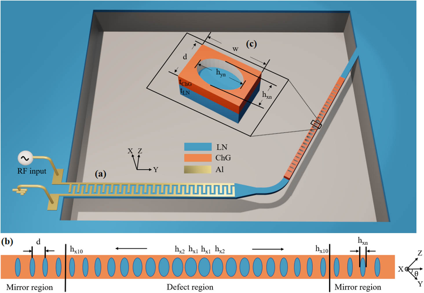
The device structure of the heterogeneous-integration piezo-optomechanical transducer is shown in Fig. 1(a), and consists of an IDT-loaded suspended wavelength-scale mechanical waveguide and a heterogeneous OMC cavity. Figure 1(b) shows the top view of the designed heterogeneous OMC cavity, composed of a PC nanobeam made of ChG and a supported X-cut TFLN slab. The PC nanobeam includes one defect and two mirror regions, consisting of a series of regular elliptical air holes. Figure 1(c) shows the unit structure of the heterogeneous OMC. Herein, the heights of the ChG PC nanobeam and the TFLN slab are denoted as and , respectively, and the width of the nanobeam is denoted as . In the mirror region, the short axes and the long axes of the elliptical air holes are constant, and in the defect region, the short axes of the air holes are gradually decreased from to at a quadratic rate to simplify the OMC design. The lattice constant between the adjacent elliptical air holes is denoted as .
Figure 1.Schematic diagram of a piezo-optomechanical transducer with a TFLN-ChG heterogeneous OMC cavity coupled by a wavelength-scale mechanical waveguide.
The mirror regions on both sides can reflect the optical and acoustic waves corresponding to the band structures, while the defect region can confine these waves reflected from the mirror regions into the cavity center forming the optical and acoustic resonances due to the slow variations of the short axes. The excitation of the optical resonance mode in the suspended heterogeneous OMC cavity can be realized by lateral coupling configuration using an on-chip waveguide placed next to the OMC. The introduction of the acoustic breathing mode can be completed by the conversion of guided acoustic modes in a wavelength-scale mechanical waveguide using IDT-driven piezoelectric transduction.
For an OMC cavity, the optical and acoustic resonance modes can interact with each other in the defect region. To characterize the interaction strength between both physical fields, the optomechanical coupling rate as a key merit is chosen to estimate the perturbation from the mechanical vibration, which is defined as the amount of change in optical frequency due to the zero-point motion of the mechanical mode, as shown in Eq. (1) [34], where is the angular frequency of the optical mode, is the normalized amplitude of the displacement field, and is the zero-point motion of the acoustic mode. It can be calculated by considering the contributions from the moving boundary (MB) and the photoelastic (PE) effects. The detailed calculation formulas are shown in Appendix A.
Figure 2(a) shows the variations of at the different for both fundamental transverse electric (TE) and transverse magnetic (TM) modes in the heterogeneous OMC. The insets show the cross-sectional electrical fields of both optical resonance modes at plane . It can be seen that the decreases with the increase of , and the fundamental TM mode has a larger than TE mode, which is different from the previous conclusions of the most conventional OMC cavities [12,13,31,35]. It is the reason that the PE effect of ChG film has a dominant function in , and the larger confinement factor of mode in ChG waveguide, the more significant for this phenomenon. The TM mode has a larger energy arrangement in the ChG waveguide with thickness of 540 nm, resulting in a more superior overlap with the confined acoustic mode than TE mode due to the smaller acoustic velocity of the ChG in comparison with the LN. To reveal the effect of the LN anisotropy on the optomechanical coupling, we calculate the variations of the along the different in-plane directions of the X-cut TFLN with a of 200 nm for the heterogeneous OMC, as presented in Fig. 2(b). The choice of the TFLN with of 200 nm in the simulation is attributed to its good of 340 kHz for TM mode, as indicated by the dashed line. Herein, the is defined as the angle between the crystal axis and the acoustic wave transmission direction in the heterogeneous OMC, which is changed from 0° to 180° covering a cycle. For the TM mode, the maximum of 338 kHz is located at the crystal direction (), and maximum of 238 kHz is around at 45° for TE mode, which is consistent with the conclusion of the TM surpassing the TE mode found before. In addition, we also study the influence of on the optomechanical coupling, as shown in Fig. 2(c). When the transmission direction of the acoustic wave is determined along the crystal axis, the maximum of approximately 361 kHz is located around of 520 nm. With the increase of , the tends to monotonously reduce in the heterogeneous OMC due to the enhancement of the opposite contribution from TFLN on the total . Considering the match of mechanical frequencies of guided modes with the IDT source over the suspended XY TFLN slab, the ChG nanobeam with the of 540 nm is chosen to form high factor optical resonance, as shown in Fig. 2(d). It can be found that the optical factor of the TM mode in the heterogeneous OMC is calculated up to near the wavelength of 1460 nm. This indicates that much more optical energy is confined in the ChG nanobeam to participate in the optical oscillating with the increase of . By further engineering the geometries of the heterogeneous OMC, the optical resonance wavelength of the device can be easily extended to the C-band. In the following application, a trade-off parameter is utilized to couple the wavelength-scale mechanical waveguide.
Figure 2.(a) Effects of on for both fundamental TE and TM modes in the heterogeneous OMC. (b) Variations of the along the different in-plane orientations in X-cut TFLN with respect to the heterogeneous OMC. (c) Effects of the on for both fundamental TE and TM modes in the heterogeneous OMC. (d) Variations of the optical factors and resonant wavelengths with the increase of the .
Based on these optimized parameters, we calculate the photonic and phononic bands of the one-dimensional (1D) heterogeneous OMC for the mirror region using the finite element simulation. The detailed structural parameters used in the calculations are shown in Table 1. Figure 3(a) shows the photonic band of the fundamental TM mode in the heterogeneous OMC, where the region under the green line reflects the dispersion curves of the guided optical modes propagating in the heterogeneous OMC, as indicated by the red lines. The gray area in the photonic band diagram represents an optical bandgap from 199 to 226 THz at the point, which means the guided optical waves during this bandgap will be reflected by the mirror region. As a representative optical mode, the defect mode with a frequency of 205.7 THz is introduced by carefully engineering the geometries of the elliptical air holes in the defect region, as denoted by the dashed line. The normalized electric field component corresponding to the TM mode is shown in Fig. 3(c), which presents that the most optical resonance mode is well confined in the defect region. The optical factor corresponding to the mode is calculated to be with the optimized PC periods of 21 in the mirror region. We also present the phononic band of the semi--symmetric acoustic modes corresponding to the acoustic defect mode (as denoted by the dashed line) based on the same waveguide structure, as shown in Fig. 3(b). Similar to the photonic band, the phononic bandgap is created from 0.786 to 1.159 GHz at point. The blue line represents the motion band of the guided acoustic L0 mode, which is distinctly designed to excite the defect mode, as shown by the black arrow indicator. Figure 3(d) shows the normalized displacement field diagram of the defect mode with resonant frequency of 1.1179 GHz, satisfying the sideband-resolved regime. It emphasizes that the acoustic breathing mode is mainly focused on the center of the defect region, which dominates the overlap area of photon–phonon interaction. The mechanical factor is estimated to be 300, approximately ten times lower than that of its counterpart reported in Ref. [26]. Herein, the density, Young’s modulus, and Poisson’s ratio of the ChG film are set to be , 24 GPa, and 0.285, respectively.
Parameters of the Heterogeneous OMC Cavity Coupled by a Wavelength-Scale Mechanical Waveguide
Heterogeneous OMC
Mechanical Waveguide
Parameter
Value
Parameter
Value
300 nm
2.621 μm
200 nm
23.5
600 nm
1.752 μm
430 nm
3.317 μm
540 nm
90°
200 nm
100 nm
830 nm
10 μm
Figure 3.(a) Photonic band of the TM modes corresponding to the mirror region in heterogeneous OMC around the frequency of 200 THz. (b) Phononic band of -symmetric acoustic modes corresponding to the mirror region in heterogeneous OMC around the frequency of 1.11 GHz. The arrow indicates the cross point between the guided L0 mode (blue line) and excited breathing mode in the heterogeneous OMC. (c) Normalized component of the optical defect mode. (d) Normalized displacement field of the acoustic defect mode.
3. DESIGN OF A WAVELENGTH-SCALE MECHANICAL WAVEGUIDE
To excite the breathing mode in the heterogeneous OMC cavity, an IDT-loaded suspended LN mechanical waveguide is carefully designed to control the transmission of the guided acoustic wave modes. The IDT-loaded mechanical waveguide is composed of four segmented waveguides including the IDT region, LN linear horn, narrow waveguide, and LN-ChG heterogeneous waveguide. The schematic diagram of the mechanical waveguide is shown in Fig. 1(a). To match the eigenfrequency of the breathing mode, a proper IDT made of aluminum (Al) with an aperture of 1.752 μm is precisely engineered over an LN plate waveguide with a width of 3.317 μm. The number and thickness of the Al electrode are 23.5 pairs and 100 nm, respectively, and the excited acoustic wave wavelength of the IDT is designed to be 2.621 μm. The LN linear horn is designed to match the width of the heterogeneous OMC. The length of the LN linear horn is set to be 10 μm. The whole parameters are provided in Table 1. The injected RF electrical signal is applied to the IDT to generate the guided acoustic wave modes in the LN plate waveguide with thickness of 200 nm including the Lamb waves, longitudinal waves, and horizontal shear waves using the piezoelectric effect. These guided acoustic waves are scattered into the narrow LN mechanical waveguide region by linear horn. The conversion efficiency of the whole guided acoustic wave modes is calculated to be approximately 19.1% relative to the unit microwave input power at around 1.15 GHz, indicating that the rest of the microwave energy is lost to dissipation and reflection.
To clarify the energy distribution of the guided acoustic modes, we analyze the phononic band corresponding to the narrow XZ LN mechanical waveguide due to the large along this direction, as shown in Fig. 4(a). It can be seen that there are four guided acoustic modes in the vicinity of the breathing mode frequency indicated by the dashed line, including fundamental Lamb (A0), first-order Lamb (A1), SH0, and L0. By the eigenmode analysis, we calculate the power decomposition of the four guided acoustic modes confined in the narrow LN mechanical waveguide referring to Ref. [36]. The detailed calculation expressions are shown in Appendix B. Corresponding acoustic modes are drawn in Fig. 6 in Appendix C. The results are presented in Fig. 4(c) by choosing the different mechanical waveguide cross sections. It can be seen that 91% acoustic energy is arranged in dominant SH0 mode, which is well maintained after crossing the linear horn. The mode fractions of the other modes are less than 9%, indicating that 17.38% energy from the loaded RF power is converted into SH0 mode in the narrow LN mechanical waveguide. When the guided acoustic modes propagate through the TFLN-ChG heterogeneous mechanical waveguide, the pathways and fractions of the guided acoustic modes are significantly varied due to the scattering from the ChG waveguide. Similarly, we also estimate the phononic band corresponding to the TFLN-ChG heterogeneous mechanical waveguide region, as shown in Fig. 4(b). More complex band distributions appear in the heterogeneous waveguide at around 1.15 GHz, indicating that the confinement of guided acoustic modes is dragged into the ChG waveguide, benefiting from its small acoustic velocity. The L0 mode is clearly excited at the point via the scattering of the heterogeneous waveguide. Subsequently, we calculate the power fractions of the converted acoustic modes corresponding to the initiating terminal of the TFLN-ChG heterogeneous waveguide, as shown in Fig. 4(d). It is interesting that the partial SH0 mode is converted into the L0, which is intentionally designed to couple with the breathing mode in heterogeneous OMC. It can be estimated that 18.4% acoustic energy is scattered into L0 mode with respect to the acoustic wave power in the narrow LN mechanical waveguide, indicating that the rest of the energy is lost to the dissipation in the TFLN-ChG heterogeneous waveguide interface. The successful excitation of the L0 mode with mode fraction of 80% demonstrates the scattering mechanism of the smooth ChG waveguide, illustrating that 3.51% energy from the applied RF power is transferred into the mechanical motion in L0 mode. This driven energy is approximately six times higher than that of dominant L1 mode in Ref. [26]. The energy conversion efficiency could be further improved by creatively designing the coupling structure of the initiating terminal of the TFLN-ChG heterogeneous waveguide and optimizing impedance match of the loaded IDT.
Figure 4.Phononic bands of guided acoustic modes corresponding to (a) the narrow XZ LN mechanical waveguide and (b) the initiating terminal of the TFLN-ChG heterogeneous mechanical waveguide at around 1 GHz in heterogeneous piezo-optomechanical transducer. Mode fractions of guided acoustic modes corresponding to (c) the narrow XZ LN mechanical waveguide and (d) the initiating terminal of the TFLN-ChG mechanical waveguide in heterogeneous transducer.
4. DEMONSTRATION OF A HETEROGENEOUS PIEZO-OPTOMECHANICAL TRANSDUCER
Based on the design and optimization of the heterogeneous OMC and the wavelength-scale mechanical waveguide, as a proof, we simulate the excitation and propagation of the guided acoustic modes confined in the heterogeneous piezo-optomechanical transducer. Figure 5(a) shows that a propagating SH0 motion is converted by an incident RF signal in the IDT-loaded LN plate waveguide region, which is well scattered into the narrow LN mechanical waveguide via a linear horn, as denoted by the black arrows. When the guided SH0 mode meets the TFLN-ChG heterogeneous mechanical waveguide, it is converted into the L0 mode, which is also demonstrated in the zoomed-in Fig. 5(c). As a result, the acoustic breathing mode in the heterogeneous OMC cavity is successfully excited by a propagating L0 in the periodic mirror region, as presented in Fig. 5(b).
Figure 5.Simulated results of the guided acoustic modes in the heterogeneous piezo-optomechanical transducer. (a) Excitation and propagation of the SH0 mode in the transducer. (b) Excitation of the breathing mode in heterogeneous OMC cavity coupled by a wavelength-scale mechanical waveguide. (c) Zoomed-in picture representing the conversion between the SH0 and L0 modes near the TFLN-ChG heterogeneous mechanical waveguide.
In conclusion, we have demonstrated a heterogeneous-integration OMC coupled by a wavelength-scale LN mechanical waveguide. The heterogeneous OMC is composed of the TFLN slab and ChG PC nanobeam together so as to make full use of excellent piezoelectric effect of the LN and superior photoelastic effect of the ChG. As a result, the geometries of the heterogeneous OMC cavity are optimized and maximum optomechanical coupling rate is calculated up to 340 kHz at 1.1197 GHz. The optical factor of the heterogeneous OMC cavity is estimated to be . To excite the acoustic resonance of the heterogeneous OMC, a wavelength-scale suspended LN mechanical waveguide is carefully designed to propagate the dominant SH0 mode, which is created using an incident RF signal in the IDT-loaded region. The scattering of the TFLN-ChG heterogeneous waveguide leads to 3.15% energy relative to the loaded RF power to be converted to the L0 mode in the heterogeneous waveguide. The acoustic breathing mode of the heterogeneous OMC cavity is successfully excited with the help of the guided L0 mode in the heterogeneous-integration region. The demonstration of the heterogeneous piezo-optomechanical transducer provides an important platform for highly efficient microwave to optical conversion.
Acknowledgment
Acknowledgment. We thank Professor Huan Li from Zhejiang University for providing helpful discussions.
Sign up for Photonics Research TOC. Get the latest issue of Photonics Research delivered right to you!Sign up now
APPENDIX A: CALCULATION OF OPTOMECHANICAL COUPLING RATE
The optomechanical coupling rate reflects the acousto-optic interaction strength in the OMC cavity. In this paper, we mainly consider the contribution of the moving boundary (MB) and the photoelastic effects.
The contribution from the MB effect is given by where is the normalized displacement field of the acoustic mode, is the unit out-of-plane normal vector, is the electric field, is the electrical displacement field, and the subscripts and denote the field components parallel and perpendicular to the surface, respectively. and are the difference between the permittivities of both materials and its inverse. Herein, we approximately calculate the TFLN as an isotropic material with a refractive index [31].
For the contribution of the PE effect, we can obtain similar result, as shown in Eq. (A2) [37]: where is the vacuum permittivity and () is the optical indicatrix. The changes of indicatrix coefficients () due to the strain () are given by where is the photoelastic tensor and is the strain tensor. For the ChG, as an isotropic material, the photoelastic coefficients (, , ) are (0.25, 0.24, 0.05). For the anisotropic LN material, the photoelastic matrix is rotated according to the crystal orientation in our device. When we choose X-cut TFLN to constitute the heterogeneous OMC with acoustic wave propagating in the direction of the crystal, the changes of indicatrix coefficients are given by
The overall optomechanical coupling rate is thus given by
APPENDIX B: POWER DECOMPOSITION OF MECHANICAL WAVEGUIDE MODES
In Fig. 4, we calculate and list the energy proportions of each acoustic mode propagating in the mechanical waveguide, and obtain the power flow density of the hybrid acoustic waves in solid state using the complex Poynting vectors of electromagnetic waves. For a two-dimensional cross-section of the mechanical waveguide, the power flow through the cross-section can be expressed as where is the stress field in a solid, and is the particle velocity field.
Using the finite element method to carry out the eigenmode analysis in the rectangular mechanical waveguide, different acoustic modes can be estimated. The propagation factor of the acoustic mode is . The power orthogonal relationship between the acoustic modes and with different propagation factors satisfies the following formulas at the same frequency: where is the intrinsic power of the mode .
In a solid module, the properties of the propagating acoustic waves satisfy the superposition of the fields,
The stress field and the particle velocity field obtained from the eigenmode analysis can be used as orthogonal basis. Consequently, the and of the actual acoustic wave propagating in the mechanical waveguide can be expressed by weighted sum in principle. The coefficients and in Eqs. (B3) and (B4) can be obtained by the following overlap integrals:
APPENDIX C: POWER ORTHOGONAL BASIS OF ACOUSTIC WAVES
It is necessary to obtain the power orthogonal basis before the mode decomposition. We use the finite element method to analyze the power orthogonal basis of the TFLN-ChG heterogeneous mechanical waveguide at 1.15 GHz; they are A0, A1, SH0, and L0, respectively, as shown in Fig. 6.
Figure 6.Four power orthogonal bases in the heterogeneous mechanical waveguide at 1.15 GHz. The color represents the dominant displacement field component, and the black arrow represents the direction in which the particle vibrates.