• NUCLEAR TECHNIQUES
  • Vol. 45, Issue 12, 120102 (2022)
Gangjia ZHAI, Xiaokang SUN, Ke XUAN, Liuguo CHEN, Chuan LI*, and Gongfa LIU
Author Affiliations
  • National Synchrotron Radiation Laboratory, University of Science and Technology of China, Hefei 230029, China
  • show less
    DOI: 10.11889/j.0253-3219.2022.hjs.45.120102 Cite this Article
    Gangjia ZHAI, Xiaokang SUN, Ke XUAN, Liuguo CHEN, Chuan LI, Gongfa LIU. The design of Hefei advanced light facility timing system[J]. NUCLEAR TECHNIQUES, 2022, 45(12): 120102 Copy Citation Text show less
    Layout of HALF
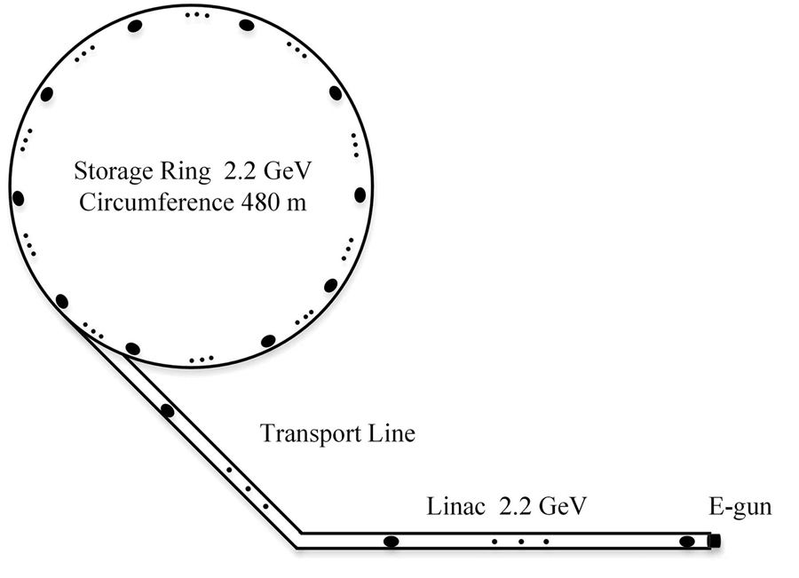
    Fig. 1. Layout of HALF
    Schematic diagram of the actual working sequence of each subsystem after receiving the trigger from the timing system (the horizontal axis only represents the chronological order)
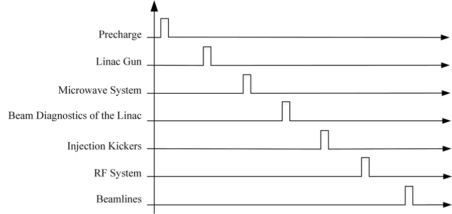
    Fig. 2. Schematic diagram of the actual working sequence of each subsystem after receiving the trigger from the timing system (the horizontal axis only represents the chronological order)
    Hardware structure diagram of timing system
    Fig. 3. Hardware structure diagram of timing system
    Schematic diagram of arbitrary bucket filling in storage ring
    Fig. 4. Schematic diagram of arbitrary bucket filling in storage ring
    Software design of timing system
    Fig. 5. Software design of timing system
    Operation interface of timing system
    Fig. 6. Operation interface of timing system
    Hardware structure diagram of the prototype system (a) and photo of a prototype system (b)
    Fig. 7. Hardware structure diagram of the prototype system (a) and photo of a prototype system (b)
    Jitter result of RF clock (arrows point to enlarged test results)
    Fig. 8. Jitter result of RF clock (arrows point to enlarged test results)
    Oscilloscope output without DC (a) and with DC (b) (arrows point to enlarged test results)
    Fig. 9. Oscilloscope output without DC (a) and with DC (b) (arrows point to enlarged test results)
    Graph of optical fiber transmission delay with temperature
    Fig. 10. Graph of optical fiber transmission delay with temperature
    Measurements of delay adjustment (a) and delay range (b) (arrows point to enlarged test results)
    Fig. 11. Measurements of delay adjustment (a) and delay range (b) (arrows point to enlarged test results)
    Test result of delay adjustment (a) and test result of pulse width adjustment (b)
    Fig. 12. Test result of delay adjustment (a) and test result of pulse width adjustment (b)
    Measurements of the first four pulse width adjustment range (a) and other pulses width range (b) (arrows point to enlarged test results)
    Fig. 13. Measurements of the first four pulse width adjustment range (a) and other pulses width range (b) (arrows point to enlarged test results)

    触发信号的抖动

    Jitter of trigger signals

    <30 ps

    触发信号延迟的调节步长

    Delay adjustment length of trigger signals

    <10 ns

    触发信号延迟的范围

    Delay range of trigger signals

    ≥1 s

    触发信号脉宽的调节步长

    Pulse width adjustment length of trigger signals

    20 ns

    触发信号脉宽的范围

    Pulse width range of trigger signals

    ≥60 μs
    Table 1. Design specifications of HALF timing system

    装置

    Facilities

    技术路线

    Technical route

    建成年份

    Completion date of construction

    MAX IVEvent timing2016
    SiriusEvent timing2019
    ESRF-EBSWhite Rabbit2019
    HEPSEvent timing建设中 Under construction
    APS-UEvent timing建设中 Under construction
    SHINEWhite Rabbit建设中 Under construction
    Table 2. The timing system of some accelerator facilities
    参数 Parameters方案一 Option one方案二 Option two
    电子枪激光频率fLaser E-Gun laser frequencyfLaser83.3 MHz79.333 MHz
    直线加速器微波频率fModu Linac microwave frequencyfModu2 998.8 MHz2 856 MHz
    储存环高频腔频率fRf Storage Ring RF FrequencyfRf499.8 MHz499.8 MHz
    谐波数H Harmonic numberH799800
    Table 3. Two frequency design schemes of injection and storage ring
    事件码 Event codes功能 Functions
    0x00空事件信号 Null event signal
    0x01光阴极微波电子枪的触发信号 Trigger signal of photocathode RF electron gun
    0x02热阴极电子枪的触发信号 Trigger signal of thermionic cathode electron gun
    0x03调制器等注入设备的触发信号 Trigger signal of injection devices such as modulator
    0x04直线加速器束流测量设备的触发信号 Trigger signal of beam diagnostics devices at Linac
    0x05储存环束流测量设备的触发信号 Trigger signal of beam diagnostics devices in storage ring
    0x7E延迟补偿信号 Delay compensation signal
    0x7F序列结束信号 End of sequence signal
    Table 4. Event code distribution of timing system

    测试项

    Test items

    无DC

    Without DC / ns

    有DC

    With DC / ns

    t15.166 0×1022.347 0×10-1
    t2-5.161 4×1022.286 0×10-1
    系统误差System error2.300 0×10-12.316 5×10⁻¹
    信号漂移Signal drift5.163 7×1023.050 0×10-3
    Table 5. Test results of DC
    Gangjia ZHAI, Xiaokang SUN, Ke XUAN, Liuguo CHEN, Chuan LI, Gongfa LIU. The design of Hefei advanced light facility timing system[J]. NUCLEAR TECHNIQUES, 2022, 45(12): 120102
    Download Citation