• Photonics Research
  • Vol. 11, Issue 1, 108 (2023)
Guocui Wang1、2, Tian Zhou1, Jianzhou Huang1, Xinke Wang2, Bin Hu1、3、*, and Yan Zhang2、4、*
Author Affiliations
  • 1Beijing Engineering Research Center for Mixed Reality and Advanced Display, School of Optics and Photonics, Beijing Institute of Technology, Beijing 100081, China
  • 2Beijing Key Laboratory of Metamaterials and Devices, Key Laboratory of Terahertz Optoelectronics, Ministry of Education, Beijing Advanced Innovation Center for Imaging Theory and Technology, Department of Physics, Capital Normal University, Beijing 100048, China
  • 3e-mail: hubin@bit.edu.cn
  • 4e-mail: yzhang@cnu.edu.cn
  • show less
    DOI: 10.1364/PRJ.475973 Cite this Article Set citation alerts
    Guocui Wang, Tian Zhou, Jianzhou Huang, Xinke Wang, Bin Hu, Yan Zhang. Moiré meta-device for flexibly controlled Bessel beam generation[J]. Photonics Research, 2023, 11(1): 108 Copy Citation Text show less
    Schematic of the proposed moiré meta-device for order-variable Bessel beams generation. The moiré meta-device is cascaded by two metasurfaces with different phase profiles. Bessel beams can be obtained after a THz beam passes through the moiré meta-device. The order of the Bessel beam can be changed by mutual rotating with a step of 20° between the two metasurfaces.
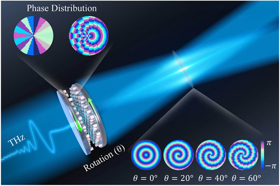
    Fig. 1. Schematic of the proposed moiré meta-device for order-variable Bessel beams generation. The moiré meta-device is cascaded by two metasurfaces with different phase profiles. Bessel beams can be obtained after a THz beam passes through the moiré meta-device. The order of the Bessel beam can be changed by mutual rotating with a step of 20° between the two metasurfaces.
    Design principle of the proposed moiré meta-device to generate order-variable Bessel beams. (a) Schematic of the combination of a flat spiral and a flat axicon. (b) Design principle of the proposed moiré meta-device to generate order-variable Bessel beams. Φ1 and Φ2 are the phase profiles of metasurface 1 and metasurface 2, respectively. Φjoint is the phase profile of the functional device to be realized. α0 is the mutual rotation angle between two metasurfaces.
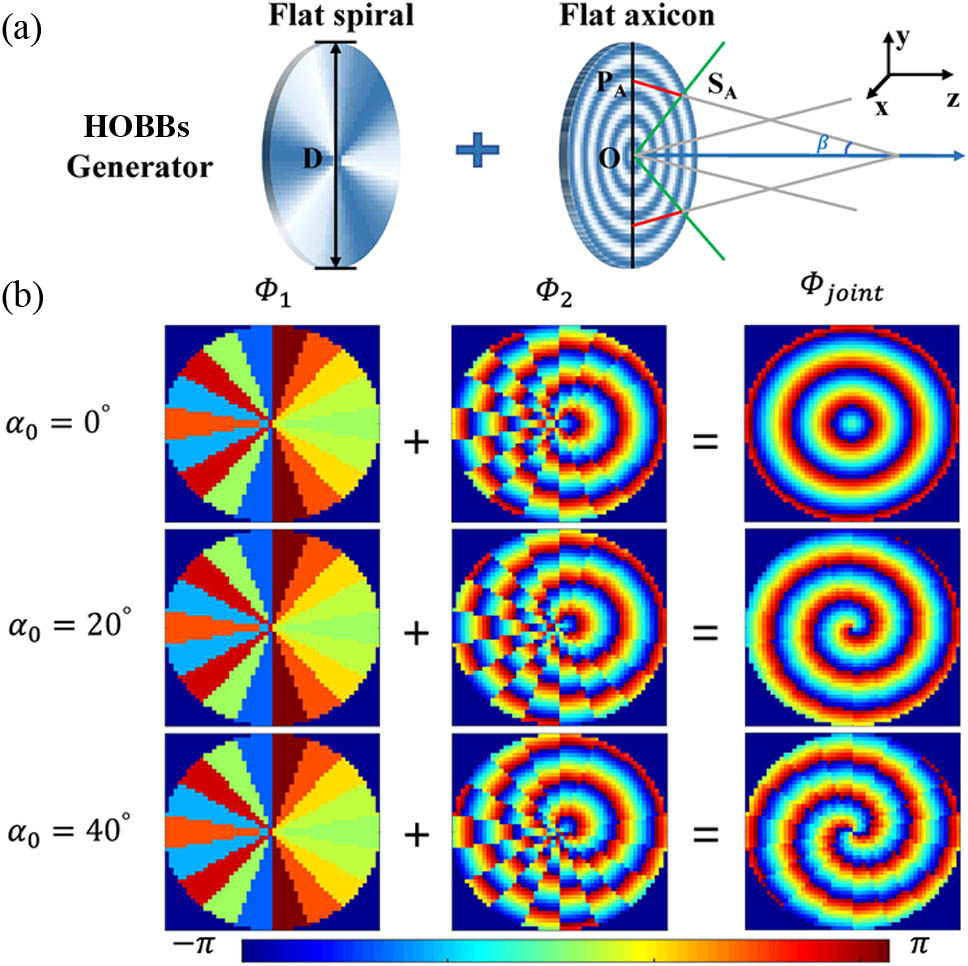
    Fig. 2. Design principle of the proposed moiré meta-device to generate order-variable Bessel beams. (a) Schematic of the combination of a flat spiral and a flat axicon. (b) Design principle of the proposed moiré meta-device to generate order-variable Bessel beams. Φ1 and Φ2 are the phase profiles of metasurface 1 and metasurface 2, respectively. Φjoint is the phase profile of the functional device to be realized. α0 is the mutual rotation angle between two metasurfaces.
    Schematic of designed processes of the metasurfaces. (a) Basic elements of the metasurface are high-resistivity silicon pillars with a height h of 300 μm and variable diameters d ranging from 30 to 180 μm on a silicon substrate with a period P of 200 μm and height H of 700 μm. (b) Transmission and phase shift of silicon pillars with different diameters at the operation frequency of 0.6 THz. (c), (d) SEM images of fabricated metasurface 1 and metasurface 2, respectively. The scale bar is 200 μm.
    Fig. 3. Schematic of designed processes of the metasurfaces. (a) Basic elements of the metasurface are high-resistivity silicon pillars with a height h of 300 μm and variable diameters d ranging from 30 to 180 μm on a silicon substrate with a period P of 200 μm and height H of 700 μm. (b) Transmission and phase shift of silicon pillars with different diameters at the operation frequency of 0.6 THz. (c), (d) SEM images of fabricated metasurface 1 and metasurface 2, respectively. The scale bar is 200 μm.
    Experimental results. (a) Schematic of experimental setup. PM, parabolic mirror; HWP, half-wave plate; P, polarizer; BS, beam splitter; QWP, quarter-wave plate; WP, Wollaston prism; and CCD, charge-coupled device. (b) Experimental and (c) simulated results for the zeroth-order Bessel beam when the mutual rotation of two metasurfaces is 0°. Two columns on the left are the normalized amplitudes on the y–z plane and the x–y plane, and on the right on the y–z plane and the x–y plane are the corresponding phase profiles. (d) Transverse amplitude and phase profiles along the horizontal white dotted cut lines across the centers of experiment and simulation results.
    Fig. 4. Experimental results. (a) Schematic of experimental setup. PM, parabolic mirror; HWP, half-wave plate; P, polarizer; BS, beam splitter; QWP, quarter-wave plate; WP, Wollaston prism; and CCD, charge-coupled device. (b) Experimental and (c) simulated results for the zeroth-order Bessel beam when the mutual rotation of two metasurfaces is 0°. Two columns on the left are the normalized amplitudes on the yz plane and the xy plane, and on the right on the yz plane and the xy plane are the corresponding phase profiles. (d) Transverse amplitude and phase profiles along the horizontal white dotted cut lines across the centers of experiment and simulation results.
    Experimental and simulated results for order-variable Bessel beam generation based on the moiré meta-device with the mutual rotation of two metasurfaces changing from 0° to 80° with a step of 20°. (a)–(b) Normalized amplitude and phase profiles measured in the experiment. (c)–(d) Normalized amplitude and phase profiles obtained in the simulation.
    Fig. 5. Experimental and simulated results for order-variable Bessel beam generation based on the moiré meta-device with the mutual rotation of two metasurfaces changing from 0° to 80° with a step of 20°. (a)–(b) Normalized amplitude and phase profiles measured in the experiment. (c)–(d) Normalized amplitude and phase profiles obtained in the simulation.
    Simulated results for nondiffraction region variable Bessel beam generation based on the moiré meta-device with the mutual rotation of two metasurfaces changing from 15° to 60° with a step of 15°. (a) Near-field phase distribution of entire 12 mm diameter cascaded metasurfaces on the plane that is 1 mm away from the device obtained using the FDTD solver and field distribution of the device along the direction of propagation on the y–z plane. (b) Cut lines across the centers of field distribution illustrated in (a).
    Fig. 6. Simulated results for nondiffraction region variable Bessel beam generation based on the moiré meta-device with the mutual rotation of two metasurfaces changing from 15° to 60° with a step of 15°. (a) Near-field phase distribution of entire 12 mm diameter cascaded metasurfaces on the plane that is 1 mm away from the device obtained using the FDTD solver and field distribution of the device along the direction of propagation on the yz plane. (b) Cut lines across the centers of field distribution illustrated in (a).
    Diagram of alignment method for two metasurfaces.
    Fig. 7. Diagram of alignment method for two metasurfaces.
    Simulation results for nondiffraction region variable higher-order Bessel beams generation based on the moiré meta-device with the mutual rotation of two metasurfaces changing from 15° to 60° with a step of 15°.
    Fig. 8. Simulation results for nondiffraction region variable higher-order Bessel beams generation based on the moiré meta-device with the mutual rotation of two metasurfaces changing from 15° to 60° with a step of 15°.
    Guocui Wang, Tian Zhou, Jianzhou Huang, Xinke Wang, Bin Hu, Yan Zhang. Moiré meta-device for flexibly controlled Bessel beam generation[J]. Photonics Research, 2023, 11(1): 108
    Download Citation