
Zhigang ZHANG, Yubin ZHAO, Kai XU, Xiang ZHENG, Qiang CHANG, Shenjie ZHAO, Zhenyu MA, Hongru JIANG, Wenfeng YANG, Xuefang HUANG, Yan WANG, Jing SHI, Hongtao HOU. Low level radio frequency controller for superconducting third harmonic cavity at SSRF[J]. NUCLEAR TECHNIQUES, 2022, 45(12): 120101
- NUCLEAR TECHNIQUES
- Vol. 45, Issue 12, 120101 (2022)
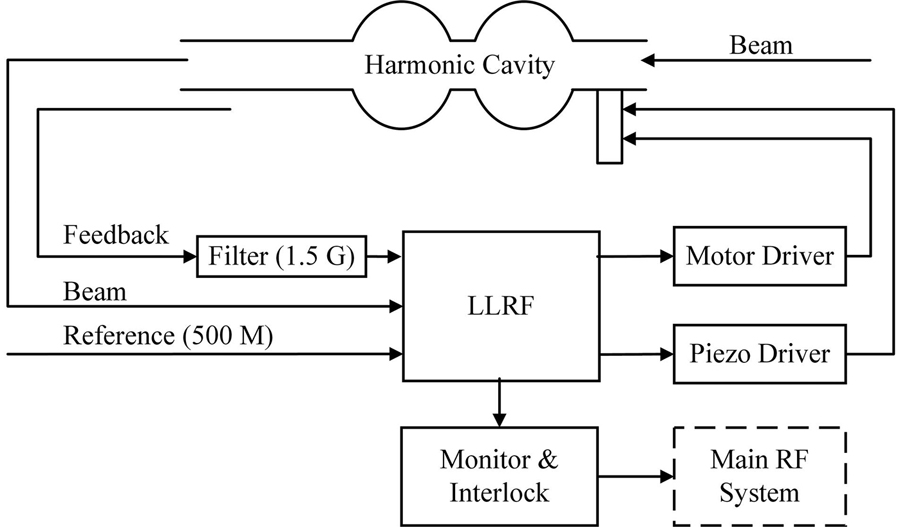
Fig. 1. Block diagram of RF system at the phase II of SSRFLLRF—Low level radio frequency, Feedback—Coupling voltage, Beam—Beam position monitor
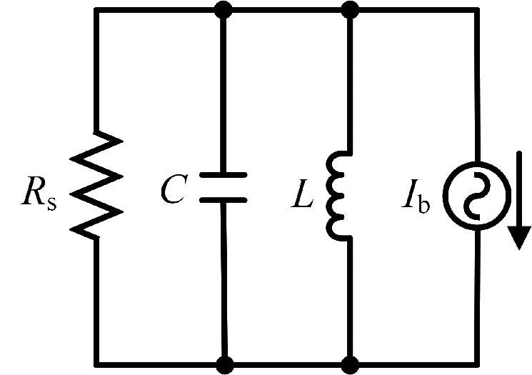
Fig. 2. Model of electrical model of resonance cavity
Fig. 3. Simulation result of the voltage of the RF system
Fig. 4. Schematic diagram of the LLRF controller in 3rd harmonic cavity at SSRF
Fig. 5. Flow chart of the measurement beam sign
Fig. 6. Data collected after detecting、filtering and amplification
Fig. 7. Experimental data of piezo voltage and displacement (increase or decrease)
Fig. 8. Brief schematic of the controller in tuner
Fig. 9. Tuning thresholds related to the status of motor (slow tuning) and piezo (fast tuning)
Fig. 10. Chart of the judgement on quench
Fig. 11. Delayed measurement of quench signal (Quench trigger, Quench to PLC, Quench to klystron in main RF system)(Color online)
Fig. 12. Amplitude stability comparison of cavity voltage (a) Open loop within ±5%, (b) Close loop within ±1%
Fig. 13. Output voltage of piezo
Fig. 14. Improvement of beam life(a) Not stretched, (b) Stretched
|
Table 1. Equipment function of SSRF phase II
|
Table 2. Parameters of SSRF harmonic cavity
|
Table 3. Analysis the relation between the difference of frequency and status of motor in close loop
|
Table 4. Test results of amplitude stability in SSRF harmonic cavity


Set citation alerts for the article
Please enter your email address

© Copyright 2018-2021 | Chinese Laser Press. All Rights Reserved 沪ICP备15018463号-20