
Dahui Wang, Yinren Shou, Pengjie Wang, Jianbo Liu, Zhusong Mei, Zhengxuan Cao, Jianmin Zhang, Pengling Yang, Guobin Feng, Shiyou Chen, Yanying Zhao, Joerg Schreiber, Wenjun Ma, "Laser-induced damage thresholds of ultrathin targets and their constraint on laser contrast in laser-driven ion acceleration experiments," High Power Laser Sci. Eng. 8, 04000e41 (2020)
- High Power Laser Science and Engineering
- Vol. 8, Issue 4, 04000e41 (2020)
Abstract
1 Introduction
The application of chirped-pulse amplification (CPA) in solid lasers has realized the output of lasers with femtosecond duration and petawatt-class power[1,2]. Interaction of such ultra-intense laser pulses with thin foils has generated protons up to 100 MeV and carbon ions close to 600 MeV (see Refs. [3–10]), which has potential applications in the fields of hadron therapy, fast-ignition laser fusion, isotope production, and proton radiography[11–14]. In particular, when the thicknesses of the foils are in the range of several nanometers to a few tens of nanometers, quasi-monoenergetic ions can be generated in the scheme of radiation pressure acceleration (RPA)[15–17]. When ultrathin targets are used, the damage caused by the prepulse energy should be avoided. For a high-power laser pulse with a contrast of 107–109 and intensity of ~1020 W/cm2, the prepulse intensity of amplified spontaneous emission (ASE) or prepulses is in the range of 1011–1013 W/cm2, which is high enough to damage many targets and significantly influence the acceleration process[18–20]. For the upcoming 10 PW class laser facilities such as ELI[21,22], the prepulse intensity will scale up with the increasing peak power. Hence, the choice of target material that can survive the prepulse energy would be a crucial issue for laser-driven ion acceleration.
Ultrathin free-standing foils made of different materials, such as metal, graphite, diamond-like carbon (DLC), and transparent polymers, have been employed as targets in laser ion acceleration experiments for years. Kim et al. reported the generation of 93 MeV protons by using 15 nm formvar, a kind of transparent polymer, as targets irradiated by a PW laser [3]. Prencipe et al. reviewed the ultrathin targets used for ion acceleration and the corresponding fabrication techniques, emphasizing that ultrahigh laser contrast is a pre-requisite for this application[23]. The contrast of the laser pulses in many cases imposes a substantial restriction on the choice of targets. Therefore, the laser-induced damage thresholds (LIDTs) of the ultrathin targets are essential parameters that should be learned before the acceleration experiments. In general, LIDTs of the ultrathin foils are considered the same as that of corresponding bulk materials. In fact, they could be significantly different. For nanometer-thin metal foils, their thicknesses are much smaller than their heat deposition depths. The mean energy density in the foils could be significantly higher than that in corresponding bulk materials. For ultrathin dielectric foils, the existence of massive surface defects induces surface states within the bandgap and intrinsic seed carriers, which will affect the ionization and laser energy transport. It is found that, owing to the existence of the surface deffects, the LIDTs of 5–40 nm DLC foils are significantly smaller than that of bulk DLC[24]. In addition to DLC foils, systematic studies on the single-shot LIDTs of other types of free-standing ultrathin targets were still missing.
We present a study on the single-shot LIDTs of multi-type free-standing ultrathin foils for a laser pulse with wavelength of 800 nm and pulse durations from 50 fs to 200 ps. Widely used targets made of formvar, silicon nitride (SiN), aluminum (Al), amorphous carbon (a-C), and carbon nanotubes (CNTs) were tested. Our results show that the laser damage threshold fluences (DTFs) of all the ultrathin foils are significantly lower than that of corresponding bulk materials. Formvar and SiN foils have the highest DTF among the tested targets. Their DTFs scale up with the laser pulse duration. For Al, a-C, and CNT foils, the DTFs are weekly dependent on pulse duration in general. By comparing the damage intensity of the targets with the prepulse intensity of a laser system, the constraint of targets’ LIDTs on the laser contrast can be obtained in a simple way.
Sign up for High Power Laser Science and Engineering TOC. Get the latest issue of High Power Laser Science and Engineering delivered right to you!Sign up now
2 Experimental setup
The experiments were performed on 100s TW Ti:sapphire laser systems of CLAPA in Peking University and on ATLAS in Max-Planck-Institutfür Quantum Optik. Seed pulses from a Kerr-lens mode-locking oscillator were amplified in a linear regenerative amplifier followed by a booster amplifier. The laser pulses were focused onto the samples by an f/3.5 off-axis parabola (OAP) mirror, which was used to generate energetic ions or X-ray/γ-ray emission in other experiments[25]. The full width at half maximum (FWHM) diameter of the focal spot is 4.5 μm, which is measured by a microscopic imaging system equipped with a 12-bit charge-coupled device (CCD). The laser energy was controlled by using different neutral density optical filters before the compressor. All the filters were thinner than 2 mm, avoiding the effects of self-phase modulation and wavefront distortions. A pyroelectric detector PE50 (OPHIR) was used to measure the energy and calibrate the filters. The root mean square (RMS) energy stability of the laser system was typically less than 2%, and we report the average value here. The pulse duration, ranging from 50 fs to 5 ps, was adjusted by moving the diffraction grating in the compressor chamber and measured by a dispersion-minimized autocorrelator (Amplitude). Pulses with durations of 200 ps were obtained by bypassing the compressor.
The foils were positioned precisely at the focal spot controlled by a high-precision position system. After each shot, the foils were front illuminated by a collimated light source. A long working-distance microscope objective lens was driven in behind the foils to image the irradiated foils. The images were recorded by the CCD behind the lens with a high resolution[25]. The damaged area of the foils is defined by the permanent holes induced by the laser pulses on the targets. The smallest damage spot we could resolve was approximately 0.5 μm. All the measurements were performed in vacuum environment with the pressure of 3×10⁻³ Pa.
3 Methods and results
The LIDTs of 50 nm formvar, SiN, Al, a-C foils, and 50 μm free-standing CNT foams were measured in the experiments. They were fabricated by the methods of spin-coating (formvar), plasma-enhanced chemical vapor deposition (SiN), thermal deposition (Al, a-C), and chemical vapor deposition (CNT), respectively[23,26]. The CNT targets were used as near-critical-density targets in previous studies[7,10]. Their average density here is 4.5 mg/cm3. The areal density of a 50 μm CNT target is equal to an 80 nm DLC target.
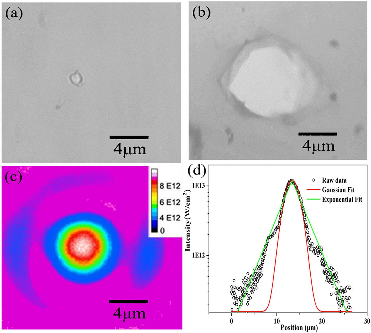
Figure 1.The damage morphologies of a formvar target under laser irradiation at the intensity of (a) 6×10¹² W/cm2 and (b) 1.1×10¹³ W/cm2. (c) The intensity distribution around the focal spot. (d) A line out of the laser intensity across the focal spot (scattered black circle), the corresponding Gaussian fit (red line), and the exponential fit (green line) of the raw data.
![]()
Figure 2.Diameter of the damaged area with respect to the laser intensity.
![]()
Figure 3.Pulse duration dependence of DTF for formvar (bule diamonds), SiN (green triangles), DLC (black stars), Al (red crosses), a-C (purple squares), and CNT (orange circles).
4 Analysis of damage mechanisms of different targets
According to their conductivity, the targets in this study can be categorized into three categories: formvar and SiN are the insulators, DLC is a semiconductor, whereas Al, a-C, and CNTs are the conductors. For insulators and semiconductors, free electrons/holes are generated through multiphoton absorption and avalanche ionization. Irradiated by the femtosecond laser pulses, damage occurs when the density of free electrons reaches the critical density
4.1 Formvar and SiN
As shown in Figure 3, DTFs of formvar are higher than that of SiN for all the pulse durations. The dependences of DTFs on the pulse durations for formvar and SiN foils are similar. The DTFs of both foils scale up with
For long pulses (
 (1)
(1)Here, δ is the avalanche coefficient.
 (2)
(2)Set the smallest k to satisfy the equation
 (3)
(3) (4)
(4)4.2 DLC
The bandgap of DLC is 3.5 eV, which distinguishes it from formvar and SiN as a semiconductor. The measurement on DLC foils shows that their DTFs are weakly dependent on the pulse duration, which is quite different from formvar and SiN. For ultrathin DLC targets fabricated by cathodic arc deposition, a large number of defects and impurities result in high initial seed electron density (ISED)[37–39]. Owing to the high ISED, avalanche ionization can be easily triggered even without enough contribution from multiphoton ionization. As a result, the DTF is determined by
4.3 Al, a-C, and CNT
For these three kinds of conductive materials, the values and the dependency on the pulse duration of DTF are similar. For simplicity, we choose Al foils for investigation. Laser energy deposition and transport inside the metal can be described by the two-temperature model[40,41]
 (5)
(5) (6)
(6)Here, the electron heat capacity
Assuming that heat is deposited into the electrons on the surface and neglecting the initial electron temperature, we have the heat deposition depth[41]
 (7)
(7) (8)
(8) (9)
(9)From Equations (7) and (9), the critical time can be derived as
 (10)
(10)For Al foils, the calculated
5 Constraint of LIDTs on the laser contrast
![]()
Figure 4.The temporal profiles of three ultraintense femtosecond laser pulses from the SULF, CoReLS, and CLAPA facilities, respectively.
| ns-ASE at 200 ps | ps-pedestal at 5 ps | fs-prepulses | |
|---|---|---|---|
| CLAPA | 1 × 10⁻¹⁰ | 1 × 10⁻⁷ | 1 × 10⁻⁸ |
| CoReLS | 5 × 10-11 | 1 × 10⁻⁷ | 1 × 10⁻⁸ |
| SULF | 5 × 10⁻¹⁰ | 1 × 10⁻⁵ | 1 × 10⁻⁸ |
Table 1. The contrast of SULF, CoReLS, and CLAPA lasers.
![]()
Figure 5.Comparison between DTIs of the tested ultrathin foils and the prepulse intensity.
Figure 5 can be used to evaluate how many PMs need to be applied to avoid prepulse-induced damage and pre-expansion for a specific kind of ultrathin target. For example, by applying 1 PM to CLAPA, 2 PMs to CoReLS, and 2 PMs to SULF, the prepulse intensity will drop by more than 2, 4, and 4 orders, respectively. The corresponding prepulse intensity histograms are drawn below the DTI histograms in Figure 5. For a specific target, if its DTIs at 50 fs/500 fs/200 ps are higher than the fs-prepulse intensity, the ps-pedestal intensity at 5 ps, and the ns-ASE intensity at 200 ps, respectively, such a target would still be intact until 5 ps before the main pulse. One can easily make the judgment by comparing the bars with the same color in the two histograms. The conclusion is that all the ultrathin foils can be safely used in CLAPA with a single PM and the CoReLS with double PMs, but only formvar can be safely used in SULF even with double PMs. For all three lasers, the dominant constraint comes from the ps-pedestal intensity. When the ps-pedestal reaches the intensity of over 1012 W/cm2, shock with speed about 10 nm/ps will be launched first in the targets[48]. Then the targets will be ionized by the fast-rising pedestal and start to expand. How such an expansion influences the ion acceleration depends on the thickness of the foil, the expansion speed, and the expansion time.
6 Conclusion
In conclusion, we have performed experimental studies on the single-shot optical damage threshold of multi-type ultrathin foils used for laser-driven ion acceleration by using laser pulses with durations from 50 fs to 200 ps. We found the damage thresholds of the free-standing ultrathin foils are significantly lower than those of corresponding bulk materials. Dielectric targets such as formvar and SiN have the highest DTF among all the tested targets. The DTFs of DLC, Al, amorphous carbon, and CNT targets are all below 0.1 J/cm2 with weak dependence on the pulse duration. The obtained damage thresholds are very valuable to help to judge whether a specific target can be safely used in experiments by comparing them with prepulse intensity of lasers in a simple diagram.
References
[1] D. Strickland, G. Mourou. Opt. Commun., 56, 219(1985).
[2] G. A. Mourou, N. J. Fisch, V. M. Malkin, Z. Toroker, E.A. Khazanov, A.M. Sergeev, T. Tajima, B. Le Garrec. Opt. Commun., 285, 720(2012).
[3] I. J. Kim, K. H. Pae, C. M. Kim, H. T. Kim, J. H. Sung, S. K. Lee, T. J. Yu, I. W. Choi, C. L. Lee, K. H. Nam, P. V. Nickles, T. M. Jeong, J. M. Lee. Phys. Rev. Lett., 111(2013).
[4] J. H. Bin, W. J. Ma, H. Y. Wang, M. J. V. Streeter, C. Kreuzer, D. Kiefer. Phys. Rev. Lett., 115(2015).
[5] S. Bolaños, J. Béard, G. Revet, S. N. Chen, S. Pikuz, E. Filippov, M. Safronova, M. Cerchez, O. Willi, M. Starodubtsev, J. Fuchs. Matter Radiat. Extremes, 4(2019).
[6] A. Higginson, R. J. Gray, M. King, R. J. Dance, S. D. R. Williamson, N. M. H. Butler, R. Wilson, R. Capdessus, C. Armstrong, J. S. Green, S. J. Hawkes, P. Martin, W. Q. Wei, S. R. Mirfayzi, X. H. Yuan, S. Kar, M. Borghesi, R. J. Clarke, D. Neely, P. McKenna. Nat. Commun., 9, 724(2018).
[7] A. Henig, S. Steinke, M. Schnürer, T. Sokollik, R. Hörlein, D. Kiefer, D. Jung, J. Schreiber, B.M. Hegelich, X.Q. Yan, J. Meyer-ter-Vehn, T. Tajima, P. V. Nickles, W. Sandner, D. Habs. Phys. Rev. Lett., 103(2009).
[8] K. Xue, Z. K. Dou, F. Wan, T. P. Yu, W. M. Wang, J. R. Ren, Q. Zhao, Y. T. Zhao, Z. F. Xu, J. X. Li. Matter Radiat. Extremes, 5(2020).
[9] W. J. Ma, I. J. Kim, J. Q. Yu, I. W. Choi, P. K. Singh, H. W. Lee, J. H. Sung, S. K. Lee, C. Lin, Q. Liao, J. G. Zhu, H. Y. Lu, B. Liu, H. Y. Wang, R. F. Xu, X. T. He, J. E. Chen, M. Zepf, J. Schreiber, X. Q. Yan, C. H. Nam. Phys. Rev. Lett., 122(2019).
[10] F. Wagner, O. Deppert, C. Brabetz, P. Fiala, A. Kleinschmidt, P. Poth. Phys. Rev. Lett., 116(2016).
[11] M. Borghesi, J. Fuchs, S. V. Bulanov, A. J. MacKinnon, P. K. Patel, M. Roth. Fusion Sci. Technol., 49, 412(2006).
[12] S. Bulanov, T. Z. Esirkepov, V. Khoroshkov, A. Kuznetsov, F. Pegoraro. Phys. Rev. A, 299, 240(2002).
[13] B. Y. Sharkov, D. H. H. Hoffmann, A. A. Golubev, Y. T. Zhao. Matter Radiat. Extremes, 1, 28(2016).
[14] E. L. Clark, K. Krushelnick, J. R. Davies, M. Zepf, M. Tatarakis, F. N. Beg, A. Machacek, P. A. Norreys, M. I. K. Santala, I. Watts, A. E. Dangor. Phys. Rev. Lett., 84, 670(2000).
[15] A. Macchi, S. Veghini, F. Pegoraro. Phys. Rev. Lett., 103(2009).
[16] F. Dollar, C. Zulick, A. G. R. Thomas, V. Chvykov, J. Davis, G. Kalinchenko. Phys. Rev. Lett., 108(2012).
[17] C. Scullion, D. Doria, L. Romagnani, A. Sgattoni, K. Naughton, D. R. Symes. Phys. Rev. Lett., 119(2017).
[18] P. McKenna, D. C. Carroll, O. Lundh, F. Nurnberg. Laser Part. Beams, 26, 591(2008).
[19] V. M. Ovchinnikov, D. W. Schumacher, M. McMahon, E. A. Chowdhury, C. D. Chen, A. Morace, R. R. Freeman. Phys. Rev. Lett., 110(2013).
[20] S. Zhao, C. Lin, H. Y. Wang, H. Y. Lu, X. T. He, J. E. Chen, T. E. Cowan, X. Q. Yan. Phys. Plasmas, 22(2015).
[21] D. L. Balabanski, R. Popescu, D. Stutman, K. A. Tanaka, O. Ur Tesileanu, C. A. Ursesc, N. V. Zamfir. Eur. Phys. Lett., 117(2017).
[22] S. Gales, K. A. Tanaka, D. L. Balabanski, F. Negoita, N. V. Zamfir. Rep. Prog. Phys, 8(2018).
[23] I. Prencipe, J. Fuchs, S. Pascarelli, D. W. Schumacher, T. E. Cowan. High Power Laser Sci. Eng, 5, e17(2017).
[24] D. H. Wang, W. J. Ma, J. H. Bin, K. Alinger, Y. R. Shou, P. J. Wang, J. B. Liu, J. G. Zhu, Z. X. Cao, Z. S. Mei, H. Y. Wang, H. Y. Lu, C. Lin, Y. Y. Zhao, J. Schreiber, X. Q. Yan. Nucl. Instrum. Methods Phys. Res. B, 436, 18(2018).
[25] Y. R. Shou, D. H. Wang, P. J. Wang, J. B. Liu, Z. X. Cao, Z. S. Mei, Y. X. Geng, J. G. Zhu, Q. Liao, Y. Y. Zhao, K. Zhu, C. Lin, H. Y. Lu, W. J. Ma, X. Q. Yan. Nucl. Instrum. Methods Phys. Res. A, 927, 236(2019).
[26] J. Szeryop, W. J. Ma, G. Bothmann, D. Hahner, M. Haug, P. Hilz, C. Kreuzer, R. Lange, S. Seuferling, M. Speicher, F. stehr, S. Stork, P. G. Thirolf, J. Schreiber, H. F. Wirth. Matter Radiat. Extreme, 4(2019).
[27] J. Krüger, W. Kautek. Adv. Polym. Sci, 168, 247(2004).
[28] J. Bonse, J. M. Wrobel, J. Krüger, W. Kautek. Appl. Phys. A, 72, 89(2001).
[29] K. Sokolowski-Tinten, W. Ziegler, D. V. D. Linde, M. P. Siegal, D. L. Overmyer. Appl. Phys. Lett., 86(2005).
[30] T. V. Kononenko, S. M. Pimenov, V. V. Kononenko, E. V. Zavedeev, V. I. Konov, G. Dumitru, V. Romano. Appl. Phys. A, 79, 543(2004).
[31] K. Mann, H. Gerhardt, G. Pfeifer, R. Wolf. Laser-Induced Damage Opt. Mater., 1624, 436(1991).
[32] B. C. Stuart, M. D. Feit, A. M. Rubenchik, B. W. Shore, M. D. Perry. Phys. Rev. Lett., 74, 2248(1995).
[33] B. C. Stuart, M. D. Feit, S. Herman, A. M. Rubenchik, B. W. Shore, M. D. Perry. Phys. Rev. B, 53, 1749(1996).
[34] D. Du, X. Liu, G. Korn, J. Squier, G. Mourou. Appl. Phys. Lett., 64, 3071(1994).
[35] M. J. Laubitz. Phys. Rev. B, 2, 2252(1970).
[36] M. Sparks. J. Appl. Phys., 47, 837(1976).
[37] G. Daminelli, S. Pentzien, A. Hertwig, J. Krüger. Appl. Phys. A, 83, 89(2006).
[38] G. A. J. Amaratunga, J. Robertson, V. S. Veerasamy, W. I. Milne, D. R. McKenzie. Diam. Relat. Mater., 4, 637(1995).
[39] E. Carpene, E. Mancini, C. Dallera, D. Schwen, C. Ronning, S. D. Silvestr. New J. Phys., 9, 404(2007).
[40] S. I. Anisimov, B. L. Kapeliovich, T. L. Perel'man, Zh. Eksp. Teor. Fiz., 66, 776(1974).
[41] P. B. Corkum, F. Brunel, N. K. Ssherman. Phys. Rev. Lett., 61, 25(1988).
[42] Z. B. Lin, L. V. Zhigilei, V. Celli. Phys. Rev. B, 77(2008).
[43] Z. X. Zhang, F. X. Wu, J. B. Hu, X. F. Yang, J. Y. Gui, P. H. Ji, X. Y. Liu, C. Wang, Y. Q. Liu, X. M. Lu. High Power Laser Sci. Eng., 8(2020).
[44] J. H. Sung, H. W. Lee, J. Y. Yoo, J. W. Yoon, C. W. Lee, J. M. Yang, Y. J. Son, Y. H. Jang, S. Ku, C. H. Nam. Opt. Lett., 42, 11(2017).
[45] I. J. Kim, K. H. Pae, I. W. Choi, C. L. Lee, H. T. Kim, H. Singhal, J. H. Sung, S. K. Lee, H. W. Lee, P. V. Nickles, T. M. Jeong, C. M. Kim, C. H. Nan. Phys. Plasmas, 23(2016).
[46] Y. X. Chu, X. Y. Liang, L. H. Yu, Y. Xu, L. Xu, L. Ma, X. M. Lu, Y. Q. Liu, Y. X. Leng, R. X. Li, Z. Z. Xu. Opt. Express, 21, 29(2013).
[47] H. Vincenti, S. Monchoce, S. Kahaly, G. Bonnaud, Ph. Martin, F. Quere. Nat. Commun., 5, 3403(2014).
[48] D. H. Wang, Y. R. Shou, P. J. Wang, J. B. Liu, C.C. Li, Z. Gong, R. H. Hu, W. J. Ma, X. Q. Yan. Sci. Rep, 8, 2536(2018).


Set citation alerts for the article
Please enter your email address

© Copyright 2018-2021 | Chinese Laser Press. All Rights Reserved 沪ICP备15018463号-20