1Key Laboratory for Micro-/Nano- Optoelectronic Devices of Ministry of Education, School of Physics and Electronics, Hunan University, Changsha 410082, China
2SK Hynix Memory Solutions, 3103 North First Street, San Jose, CA 95134, USA
In this Letter, the effects of material/structure parameters of photonic crystal (PhC) parallel waveguides on the coupling length are investigated. The results show that, increasing the effective relative permittivity of the PhC leads to a downward shift of the photonic bandgap and a variation of the coupling length. A compact PhC 1.31/1.55 μm wavelength division multiplexer (WDM)/demultiplexer with simple structure is proposed, where the output power ratios are more than 24 dB. This WDM can multiplex/demultiplex other light waves efficiently.
In the past decades, due to the photonic bandgap (PBG) and the ability to control electromagnetic wave propagation, photonic crystals (PhCs) made from micro-/nanoscale periodic dielectric materials have been intensively studied and employed to develop novel photonic devices for photonic integrated circuits (PICs)[1–5]. PhC waveguides, formed by introducing a linear defect into a perfect PhC structure, is one of the essential ingredients in PICs. 2D PhC waveguides were proposed[6] and demonstrated experimentally[7,8]. Based on this structure, many components such as Mach–Zehnder devices[9], filters[10,11], modulators[12], detectors[13], sensors[14], and directional couplers[15] can be created. A primary PhC directional coupler is formed by introducing two parallel linear defects into PhCs close to each other. Using the PhC coupler, devices like optical switches[16,17], optical diodes[18], and wavelength division multiplexer (WDM)/demultiplexers[19] can be built.
Up to now, many kinds of PhC WDMs/demultiplexers have been proposed[20–29]. Many of them are designed for 1.31/1.55 μm channels[20–27]. For the design of PhC 1.31/1.55 μm WDMs, three factors should be considered. First, this device should be compact and the coupling length should be short enough to fit the PICs. Second, the transmission and the output power ratios (OPRs) (or cross talk, extinction ratios) should be improved as high as possible to make the device efficient and reliable. Last, the structure should be simple to make the fabrication easy. The previously proposed PhC 1.31/1.55 μm WDMs are be listed in Table 1. As shown in Table 1, there are some improvements from the previous work, such as only being used to demultiplex as in Ref. [21], difficult to fabricate the structure of the resonator as in Ref. [23] and 1D-2D hybrid PhC waveguides as in Ref. [26], easy to result in the power leakage with self-imaging waveguides as in Ref. [25], and the coupling length is long as in Ref. [27]. In general, the previously proposed PhC WDMs are limited to operating only 1.31 and 1.55 μm wavelengths and cannot be applied to multiplex/demultiplex other telecom wavelengths. In addition, the effects of material/structure parameters of PhC waveguides on the coupling length for both the 1.31/1.55 μm wavelengths were not investigated. The deduced optimal parameters from these parameter-effect relations will be helpful in the fabrication of the PhC waveguides and the PhC WDMs.
Therefore, in this Letter, the material/structure parameter dependence on the coupling length is investigated and a PhC 1.31/1.55 μm WDM with a coupling length of 13.4 μm and OPRs of 24.2/24.6 dB for 1.31/1.55 μm wavelengths is proposed. The structure of this WDM, built by employing only two line-defect waveguides, is quite simple. Specifically, besides the 1.31/1.55 μm, it can also be applied for other wavelengths such as 1.37, 1.47, 1.59, and 1.61 μm. In addition, the reasons for the variations of the coupling length for the 1.31/1.55 μm wavelengths and the shift of the PBG occurred in the PhC parallel waveguides are given.
Sign up for Chinese Optics Letters TOC. Get the latest issue of Chinese Optics Letters delivered right to you!Sign up now
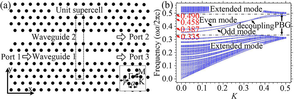
The geometrical structure of the PhC coupling waveguides is depicted in Fig. 1(a). Two parallel waveguides, oriented along the direction, are formed by removing two row rods in a perfect 2D PhC. The 2D PhC consists of dielectric rods arranged in air with a triangular lattice. The lattice constant . The dielectric rod radius and refractive index , which is set initially.
Figure 1.(a) Schematic layout of two parallel PhC coupling waveguides, and (b) a dispersion curve diagram for the PhC coupling waveguides.
A unit supercell is selected with a dashed frame in the PhC, as shown in Fig. 1(a). The dispersion curve diagram of the unit supercell shown in Fig. 1(b) is calculated by using the plane-wave expansion (PWE) method[30]. The calculation result shows that there is a TM-polarized PBG in the PhC structure. The normalized frequency [] of the PBG is from 0.335 to 0.490. The normalized frequencies of 0.458 and 0.387, corresponding to wavelengths of 1.31 and 1.55 μm, respectively, are contained in the PBG. This means that these light waves can be constrained in the PhC waveguides. The transmission of these light waves launched from Port 1 is simulated using the 2D finite-difference time-domain (FDTD) method[31] with the perfectly matched layer (PML) absorbing boundary conditions. The mesh size of the FDTD computational domain is taken as .
We consider the effects of the refractive index (radius ) of the rods in the PhC on the coupling length, the minimum periodic length of total optical power transfer between two parallel waveguides, for light waves with wavelengths of 1.31 and 1.55 μm. First, the radius of the rods is fixed as and the refractive index of the rods is changed from 2.7 to 3.1, which guarantees that the PBG of the PhC always contains both 1.31 and 1.55 μm. The calculation results are plotted in Fig. 2(a). The coupling lengths for and are labeled as and , respectively. As shown in Fig. 2(a), increases but decreases as increases. varies from 2.6 to 9.8 μm while varies from 40 to 7 μm. The variation range of is much smaller than that of . Second, the refractive index of the rods is fixed as 2.95 and the radius of the rods is changed from 0.105 to 0.125 μm. With these parameters, the PBG still contains both 1.31 and 1.55 μm. The calculation results are plotted in Fig. 2(b). As shown in Figs. 2(a) and 2(b), () is directly (inversely) proportional to the independent variables and . The variation range of is much smaller than that of . In other words, is more sensitive than to the material/structure parameters. An explanation for the variations of coupling length is given as follows.
Figure 2.(Color online) Material/structure parameter dependence on the coupling length: (a) dependence of , and (b) dependence of .
The coupled-mode theory[15,21] indicates that when two parallel and identical PhC waveguides are placed close to each other, the defect mode will be split into an even mode and an odd mode. Light wave propagation in one of the waveguides can be derived from the superposition of the even and the odd fundamental modes. Since the phase shifts between the even and the odd modes are different at different frequencies, the effects of the superposition of the even and the odd modes are different, and then make the distance of optical power transfer different, i.e., making the coupling length different. The propagation constants of the even and the odd modes are and , respectively. The phases of the even and the odd modes are and , respectively. With a switching condition the coupling length is obtained as
By employing , , can be expressed as where and are the normalized wave vectors of the even and the odd modes, respectively. is set as . From Eq. (3), is inversely proportional to . Since the value of depends on the even and the odd modes, the variation of the material/structure parameters may result in the variation of the even and the odd modes, then causing the variation of .
To demonstrate that the variation of the parameters and varies the even and the odd modes, four pairs of parameters are chosen as follows. (a1) and , which refers to the shortest and the longest in Fig. 2(a); (a2) and , which refers to the longest and the shortest in Fig. 2(a); (b1) and , which refers to the shortest and the longest in Fig. 2(b); (b2) and , which refers to the longest and the shortest in Fig. 2(b). Their dispersion curves are shown in Fig. 3, respectively. Figures 3(a) and 3(b) correspond to parameters (a1) and (a2), respectively. for and are labeled as and , respectively. As illustrated in Figs. 3(a) and 3(b), when increases from 2.7 to 3.1, the region of PBG moves downward and the curves of the even and the odd modes contained in the PBG also move downward, leading to decrease and to increase. According to Eq. (3), the increases and the decreases. Therefore, () is directly (inversely) proportional to , as shown in Fig. 2(a). Figures 3(c) and 3(d) correspond to parameters (b1) and (b2), respectively. As shown in Figs. 3(c) and 3(d), when increases from 0.105 to 0.125 μm, the region of PBG and the curves of the even and the odd modes also move downward, leading to decrease and to increase. According to Eq. (3), the increases and the decreases as well. Therefore, () is directly (inversely) proportional to , as shown in Fig. 2(b). Because is much smaller than , as shown in Figs. 3(a) and 3(c), it can be deduced from Eq. (3) that the value of is much bigger than that of . In other words, tends to be more sensitive than to the variation of and .
Figure 3.Dispersion curves diagram for the PhC waveguides with different material/structure parameters: (a) , ; (b) , ; (c) , ; (d) , .
For a fixed unit cell structure and according to electromagnetic theory , , [32], the variation of the PBG in the two cases can be explained. Increasing the or the of the rods increases the effective permittivity of a unit supercell in the PhC. Increasing decreases . Therefore, with the or the of the rods increasing, the central frequency of the PBG declines and the whole PBG shifts downward to lower frequencies.
According to the variation of the coupling length depicted in Fig. 2 and the downward shift of the PBG presented in Fig. 3, the related coupling components in the PhC can be adjusted and optimized. For example, if the material of the rods with high (or big ) is applied to build the PhC coupling waveguides but is not expected to increase, one can properly decrease the (or the ) to prevent the increase of .
For light waves with and in Port 1, if the coupling lengths and satisfy a ratio of odd integers to even integers such as , , etc., or has an infinite length while has a limited length, these light waves can be multiplexed or demultiplexed within the directional coupling waveguides[19]. From Fig. 2(a), when , , . . When , , and . . Both them satisfy the condition of demultiplexing/multiplexing. Since the in the latter case of 13.4 μm is shorter than that in the former case of 24 μm, a more compact structure can be realized by employing the latter case. Therefore, utilizing the material/structure parameters , , and , a 1.31/1.55 μm WDM with a coupling length of (22 rods are removed) can be proposed and may be built using doped InN[33–35]. InN is a promising semiconductor for the micro-nano preparation. As a typical substrate option, Si(111) can offer the lowest lattice mismatch with 8% and thermal mismatch with 5.8% to InN[33]. By plasma-assisted molecular beam epitaxy, high-quality InN can grow on the substrate Si(111) with a precise determination of the fundamental material parameters[33]. Therefore, a silicon platform[33,36] can be used as substrate to the doped InN rods in the PhC. The schematic diagram is shown in Fig. 4(a). Since , when light waves with and input from Port 1 and propagate through the distance of , the light wave with will transfer to the upper waveguide and output from Port 2, whereas the light wave with will transfer to the upper waveguide, then transfer back and output from Port 3.
Figure 4.(a) Schematic of the PhC 1.31/1.55 μm WDM, (b) the output power ratios, and (c) the steady-state field evolution patterns for light waves with different .
To analyze the transmission of different wavelengths in this structure, the OPR is generally defined as the ratio of the power at the desired output port to the residue power at the other output port[21]. Then we set , , where and are the output powers at Port 2 and Port 3, respectively. Using the FDTD method, setting two power monitors at Port 2 and Port 3 to detect the and , and changing the incident wavelength from 1.28 to 1.66 μm with step size , the steady-state OPRs are calculated and plotted in Fig. 4(b).
OPRs for and are calculated as 24.6 and 24.2 dB, respectively. From Fig. 4(b), besides the and , OPRs of other wavelengths such as , , , and are also high enough for practical application. Consequently, OPRs for , , , and are calculated as 21.0, 15.2, 20.2, and 14.4 dB, respectively. When these light waves input from Port 1 and propagate through , light waves with , , and will output from Port 2, whereas , , and will output from Port 3. Their field evolution patterns are presented in Fig. 4(c). is set as the value of input power and and are the transmission efficiencies for the light output from Port 2 and Port 3, respectively. The transmission efficiencies are calculated as 92% for , 98.6% for , 96.6% for , 94% for , 95% for , and 96% for . For the related experimental testing method, we refer to Ref. [23].
In the dispersion curves, there is a decoupling point where equals to , i.e., , . No coupling will happen between two waveguides when the frequency of the light wave is at this point. The decoupling point of this PhC WDM corresponds to normalized frequency 0.435, i.e., .
In conclusion, the variations of the coupling length with the material/structure parameters for light waves with wavelengths of 1.31/1.55 μm propagating in 2D triangular lattice PhC coupling waveguides and the variations of the PBG are analyzed and explained. The PhC 1.31/1.55 μm WDM proposed has a coupling length of 13.4 μm, which is compact for optical integration. As a multiplexer, OPRs of more than 24 dB for light waves of 1.31/1.55 μm can be achieved. This WDM can also multiplex/demultiplex other light waves with wavelengths of 1.37, 1.47, 1.59, and 1.61 μm efficiently. The structure of this WDM composed by two waveguides is quite simple.