Mei-Yan LIANG, Zhu-Yun REN, Guang-Hui LI, Cun-Lin ZHANG, Aly E Fathy. THz ISAR imaging using GPU-accelerated phase compensated back projection algorithm[J]. Journal of Infrared and Millimeter Waves, 2022, 41(2): 448
Copy Citation Text
Here, we present our implementation of two-dimensional (2D) high-resolution inverse synthetic aperture radar (ISAR) imaging using a 0.22 THz stepped-frequency (SF) radar system. The system is suitable for both near- and far-field imaging with a synthesis bandwidth of 12 GHz. The radar can provide highly accurate range and cross-range results in the near field, and its ISAR image can reach centimeter-level resolution upon using a phase-compensated Back-Projection algorithm (BP algorithm). These BP-realized results indicate that THz ISAR imaging can achieve both higher precision and finer resolution when compared to previously demonstrated range-doppler (RD) results with the same SFCW radar setup. To accelerate BP’s relatively slow image retrieval process, we employ accelerated platforms based on a graph-processing unit (GPU). Such success should pave the way for further research on near-field high-resolution radar imaging especially at THz/sub-millimeter bands.
To date,THz/sub-millimeter waves have been pursued for a wide range of applications including communications,safety inspection,and high-resolution imaging. The Terahertz(THz)frequency band(0.1 to 10 THz)has become of high interest due to its remarkably wide bandwidth,which practically translates to fine spatial resolution and high performance imaging. The desirable performance features of the THz band are due to the technology’s use of wide bandwidth receivers and highly directional antennas[1-2]. On the other hand,when compared to the LIDAR system,THz imaging is still unique as it allows for relatively deeper penetration even in smoky and/or dusty environments,which is ideal for high resolution imaging on a battlefield,for instance. Furthermore,the THz radar system can be employed for anti-jamming and anti-stealth purposes,which would be an improvement over existing electronic warfare tactics that still lie in the infrared or microwave bands. Subsequently,THz radar systems have attracted government,academic and commercial sectors to explore their vast range of applications.
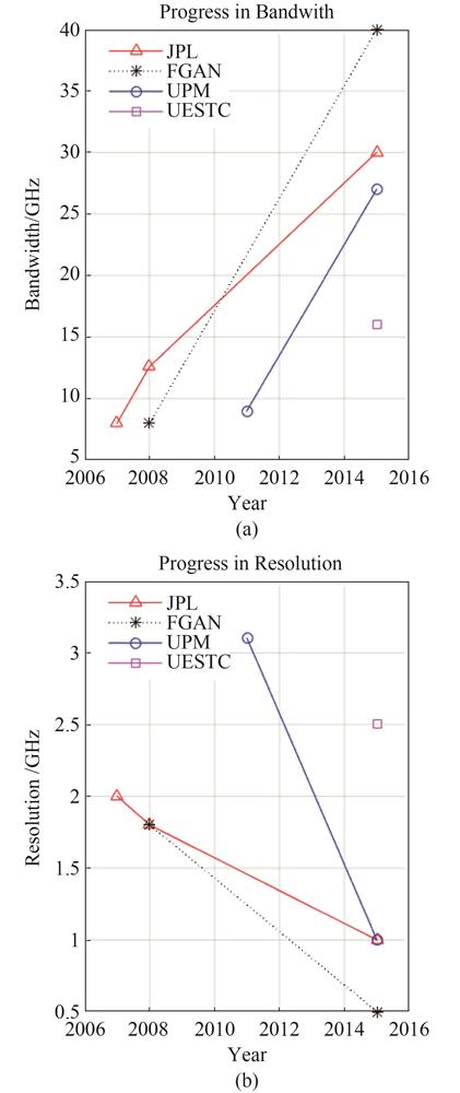
Experimental THz radar systems have been proposed and studied by many organizations over the past decade[3-4],including Jet Propulsion Laboratory(JPL)[5-9],FGAN[10-14],Universidad Politécnica de Madrid(UPM)in Spain[15-17] and University of Electronic Science and Technology of China(UESTC)[18]. Multi-input multi-output(MIMO)imaging has also been explored,such as the 340 GHz system developed by the China Academy of Engineering Physics in 2018. This system can be used for body security detection and has achieved millimeter-scale resolution with a bandwidth of 16 GHz,which is quite useful in 3D scan imaging[19]. In addition to these forerunners,more and more organizations have begun to develop their own THz radar systems resulting in remarkable achievements thus far[20-22]. The progress of THz radar system development is summarized in Table I and Fig. 1. Figure 1 depicts the steady progress of THz radar systems in terms of continuous widening of THz bandwidth and higher resolution imaging.
Figure 1.The progress of THz radar system(a)bandwidth,(b)resolution
Typically,frequency-modulated continuous wave(FMCW)and stepped-frequency continuous wave(SFCW)signals are utilized in radar systems as indicated in Table I. These two waveforms have many merits and would cover various applications. Most of the current radar systems use FMCW signals,as these signals tend to achieve relatively higher transmitted power. However,this comes at a significantly higher cost of the radar system’s sampling devices,given that these systems operate in the THz frequency range and require stringent I and Q channel calibration. On the other hand,the SFCW signal consists of a series of pulses with linearly-increasing frequency. As a result,it is convenient to measure the phase and amplitude of each transmitted sub-pulse and use the inverse Fourier transform(IFFT)of these data to build a time domain profile. Furthermore,it is relatively simple to simultaneously synthesize large bandwidth and reduce A/D sampling rate challenge for SFCW signals. Here,we leverage and adapt these features of THz SFCW radar systems for high-resolution ISAR imaging.
Generally,there are two ways to generate THz signals:by converting microwave frequencies or by down-converting optical signals. For the first group,the THz systems under 350 GHz(low frequency-THz),are based on up-conversion of microwave frequencies and features a relatively-high transmitting power advantage. Hence,they have great potential for remote sensing applications. Meanwhile,the second group,THz systems above 350 GHz(high frequency-THz),often uses optical methods to generate their signals. When using optical methods,it is easier to acquire a wide bandwidth,but the transmitted power is relatively low. In our effort here,we up-convert microwave frequencies to achieve higher transmitted power levels to build a 0.22 THz SFCW ISAR imaging radar.
Previously in Ref.[23],a 0.22 THz ISAR image was demonstrated using a Range-Doppler(RD)algorithm,but the imaging error in the azimuth direction was relatively large due to a significant phase error that seriously affected the image quality. Generally,BP can reach high accuracy and resolution in both range and azimuth directions within both the far and near fields by utilizing a phase compensation scheme. Here,we utilize a back projection(BP)algorithm for THz ISAR image reconstruction,as the object is practically in the near field.
1 0.22 THz radar system and experiments
1.1 developed 0.22 THz radar system
Our SFCW THz ISAR imaging radar spans 214 GHz to 226 GHz. Hence,the 12 GHz synthetic bandwidth should theoretically lead to a 1.25 cm range resolution. Figure 2 shows the block diagram of the 0.22 THz radar system,which consists of five modules:the frequency source,the coherent local oscillator(LO),the RF front-end,the intermediate frequency(IF)module,and the signal processor module.
Figure 2.The block diagram of the 0.22 THz radar system
As shown in Fig. 2,the frequency hopping source is controlled by an FPGA to generate a signal within the 2.18 GHz to 3.203 GHz frequency range with a 1 MHz step size,i.e. 1024 steps comprise the frame. A phase-locked loop(PLL)with low phase noise is used to cover this wideband and is controlled using a programmable frequency division factor. The PLL synthesizer also has low spur characteristics and provides short frequency hopping time for each pulse of less than 80 µs. In order to drive the transceiver chain,this signal is amplified and split into two channels. These two channels are mixed with an LO,which uses a(15.06+0.580)GHz for the TX and up-converts the signal to Ku-band or down-converts the received signal to baseband in the RX chain. After that,the RF front-end uses frequency multipliers to generate the THz signals,i.e. the Ku-band signal is multiplied by a factor of 12 using Schottky diode multipliers. The multiplication circuits have the advantage of using a low master oscillator frequency,expanding the bandwidth of the RF signals and generating the SFCW radar signal efficiently. The THz transmitted power is 7 dBm here,which is relatively high. In the receiving chain,a combination of harmonic mixing and super heterodyne receiver technology is used to generate the 1st and 2nd IF signals at 780 MHz and 60 MHz,respectively. To achieve a wide-dynamic range,a 30 dB auto gain control attenuator is added in the chain for near and far field object detection. After amplification and filtering,the data are collected using a 14 bit ADC and demodulated by an I/Q demodulator. Finally,the data are transmitted to a PC via Ethernet for further processing. The imaging parameters of the 0.22 THz SFCW radar are summarized in Table 2.
Central frequency()
0.22 THz
Frequency range
(220±6)GHz
operating mode
ISAR imaging
Output Power(P)
7 dBm
Waveform
SFCW
Frequency step size()
12 MHz
Total bandwidth(B)
12 GHz
Number of steps(N)
1 024
Pulse width(τ)
100 ns
Pulse repetition time in a burst(T)
60 µs
Burst number(M)
312
Polarization
H-H,V-V
Range resolution()
3 cm
Theoretical resolution
1.25 cm
Dynamic range of receiver
> 50 dB
Noise figure of receiver
<12 dB
IF sampling rate
60 MHz
Table 2. Design parameters of 0.22 THz SF radar system
1.2 Experimental setup of the 0.22 THz ISAR imaging scenario
The 0.22 THz ISAR imaging experiment setup is shown in Figs. (3-4). In Fig. 3,we can see the radar system,the turntable and two corner reflectors placed inside a microwave chamber. The two corner reflectors are on top of the turntable for ISAR scanning. In the experiment,the THz radar transmits a stepped-frequency signal to the target,and the turntable starts the rotary scanning simultaneously. Meanwhile,the speed of the turntable rotation and radar frame scanning signals must be synchronized. The number of bursts in the transmitted signal is M,which is composed of N sub-pulses in each burst. After each 2D scan,the THz echoes are collected by an ADC and transmitted to the host computer. Therefore,an N×M echo matrix is formed for further processing. In order to improve image resolution and accuracy in the near field,a BP algorithm is utilized to reconstruct the ISAR image after collecting all the data.
Figure 3.Experimental model of 0.22 THz ISAR imaging
The theoretical range resolution (Δδy)is related to the bandwidth of the radiated THz SFCW waveform and is estimated using
cm ,
where c is the speed of light,N = 1024, is the frequency step size, MHz,and B is the synthetic bandwidth( GHz).
The resolution in azimuth (Δδx)depends on the accumulating rotatory angle of the turntable(Θ)in the whole imaging process,which is given by
,
where is the wavelength of the radar system,M is the number of bursts that the THz radar has transmitted in one scan(here,M =312),and is the angle step of the turntable between successive bursts.
For high quality ISAR images,the range and azimuth resolutions should be approximately the same(). Therefore,the accumulating angle in azimuth(Θ)theoretically should be 3.125°(rad),based on a resolution of 1.25 cm. However,in our experiment,we used 4° instead to simplify the whole control process. Thus,the rotary step in the imaging process is 0.01°(rad),which might cause a slight image distortion but has been neglected here. In this setup,too,the imaging range between the radar system and the center of the rotary turntable is R(R= 6.4 m).
In the above experiment,the turntable takes approximately 20 seconds to complete one 2D scan. However,if you add the times for A/D sampling,signal pre-processing on-board,and the data transmission,it takes over 40 seconds to complete. Hence,THz ISAR imaging cannot realize real-time processing. The received data volume of each ISAR image is about 12 MB for a matrix of1024×312in size. The collected data are then processed by MATLAB using the BP algorithm on the host computer.
2 BP algorithm for ISAR imaging
2.1 Principle of BP algorithm
Back-projection is a space-domain algorithm that is applied to reconstruct SAR/ISAR images using radar echo signals. In this paper,the theoretical imaging model is based on two isolated scattering points that are illuminated by the 0.22 THz SFCW radar system as illustrated in Fig. 5. In the utilized THz radar system,two gold plated-horn antennas are used for bistatic operation of the transmit and receive signals in the space,and the two antennas are very close to each other. Therefore,we will base our calculations on their center point O to simplify calculations.
The antennas array illuminates the scene with an SFCW radar signal s(t). If we assume that p is one of the scattering points and is located at a position in the planar Cartesian coordinates (x,y),then let us denote the distance between the antenna and the target point p on the ith step. The complex reflectivity of the target is denoted here as ,where i is the rotation step that ranges from 1 to M (M is the number of rotation angles M=312). Then,
as shown in Fig. 5,the echo signal of the scattering point p is given by
(i=1, 2, 3…M) ,
where is the two-path propagation delay;as the signal travels from the transmitter to the target in the ith step. the time delay τi is given by
,
assuming the target is located at
Thus,the received signal at the ith rotation step of the whole region D is
.
This process is repeated until the turntable has been rotated sequentially and we have covered all required rotations steps.
Given that the imaging region is divided into a finite number of pixels in range and azimuth directions,the entire echo signals are back projected to the destination region,where the imaging reconstruction process using BP algorithm is conducted as illustrated in Fig. 6.
Figure 6.Image reconstruction process using BP algorithm
The complex composite signal corresponding to the image of the pixel located at is given by
.
The above process is repeated until all the pixels of the region D(2 m×2 m here)are covered and recorded to reconstruct the whole ISAR image.
2.2 0.22 THz ISAR imaging process using phase compensated BP algorithm
The BP algorithm,generally,coherently integrates the radar echo data over each position of the target to reconstruct the ISAR image. The BP algorithm is relatively accurate for ISAR imaging and can attain higher precision in both range and azimuth directions after phase compensation while providing fine resolution. The imaging process using BP algorithm is summarized as follows:
1)Utilize the recorded I-channel and Q-channel data to synthesize an N×M echo- matrix(Fig. 6)accounting for their amplitude and phase;the rows and columns of echo- matrix represent the sampled echo in range direction and frame number,respectively;
2)Provide a phase compensation for the echo matrix,where the process of the phase compensation is indicated in the following four steps:
a)Extract phase information in the range direction from the echo matrix using φ = arctan-1(Q/I);
b)Use linear fitting of the phase of the echo matrix in the range direction;given that the THz waveform is a stepped-frequency signal and the phase of the signal should vary linearly;
c)Calculate the phase difference between the fitted signal and the original echo matrix,then the correction phase δmn is obtained(m=1…M,n=1…N);
d)Correct the echo matrix by multiplying each element of the original matrix by the corresponding phase factor exp(jδmn);
3)Mesh the destination area into a square matrix according to the radar imaging area(2 m×2 m)and the theoretical range resolution of the 0.22 THz radar system[22]. Thus,a grid size of 401×401 is selected for ISAR imaging. Typically,the resolution of the radar imaging gridding should be 2-4 times the theoretical resolution,i.e.,the resolution should be between 3- 6.25 mm;therefore,a 5 mm was selected here.
4)Calculate the distances between the antenna and all the divided grids of the destination area and repeat for each rotation angle step. Then,back project the N×M echo matrix to the meshed grid according to the calculated distances and observation angles of the radar. The number of the angle steps in this experiment is 312. Thus,312 projected matrices with a size of 401×401 are obtained in this imaging process.
5)Coherently accumulate the 312-stack of projected matrices to form the THz ISAR image.
A flow chart depicting the overall imaging process using BP algorithm is shown in Fig. 7.
The THz ISAR experiment was carried out in an antenna chamber(shown in Figs. 8-9)utilizing a 0.22 THz radar system corresponding to a wavelength of 1.36 mm. Fig. 9 shows the trihedral corner reflectors which are placed on the turntable with absorbing materials around them. The length of the corner reflector is b,which measures 12 cm. The range between the turntable rotation center and the radar is R,which should be m in the far field to allow for proper implementation of the RD algorithm. However,the actual distance R is about 6.4 m in this experiment,meaning that the far-field condition is not satisfied. Hence,BP algorithm is implemented here to reconstruct high quality THz ISAR images,as BP can be applied in near-field imaging as well.
Figure 8.A photograph of the 0.22 THz radar system
As indicated in the flow chart in Fig. 7,the 1024×312 raw echo matrix is represented by the I-channel and Q-channel data. Subsequently,the raw echo matrix is back projected into the destination area(2m×2m)according to the range and the observation angle. Thus,a stack of 312 projected matrices(one for each rotation angle)are formed and coherently integrated to reconstruct the THz ISAR image in the spatial domain. Due to the large amount of repeated calculations required when using the BP algorithm,the reconstruction time of the THz ISAR image is too long,about 23 minutes with Intel ® core i7 Processor,constituting a major drawback for this method. The acceleration of this method will be discussed in section B.
We have run two experiments and implemented the BP algorithm on the imaging data for two cases;one for a single corner reflector(Fig. 10)and the second with two corner reflectors as shown in Fig. 11. Each corner reflector has a 26.72 dBsm RCS.
Figure 10.ISAR imaging result for a corner reflector
From Fig. 10,it is obvious that the corner reflector image is not well focused before phase compensation,but the post-phase compensation depicted in Fig. 11 indicates that the breakpoints have significantly disappeared,and the image quality has clearly improved.
2)Two corner reflector case
While the results of the two reflectors before phase compensation in Fig. 12 indicate that the distances between the two corner reflectors are 0.11 m in the range direction and 0.19 m in the azimuth direction,the corresponding actual physical distances are 0.12 m and 0.15 m in the range and azimuth respectively. Thus,there is an imaging error in the range direction of(-1)cm and in the azimuth direction of(+4)cm. This error is related to the non-linear phase performance of the reflected echo signals along the range direction,which greatly deteriorates the ISAR image accuracy. Furthermore,some breakpoints are noticeable,as shown in Figs. 10 and 12. However,after phase compensation,Fig. 13 shows the distances between the two corner reflectors in the ISAR image:0.11 m in the range direction,and 0.16 m in the azimuth direction. This means that the imaging errors in the range/azimuth directions are both within 1 cm when phase-compensated BP algorithm is utilized. These results indicate that the resolution of the THz ISAR images can reach centimeter-scale resolution,and the imaging accuracy can be greatly improved by using the phase-compensated BP algorithm.
Figure 12.ISAR imaging result for two corner reflectors
As previously mentioned,the ISAR image reconstruction time is relatively long using i7 processor. However,this process can be significantly accelerated,as the imaging process of BP requires repeatedly back projecting the echo matrix to a 401×401 grid column by column. Specifically,parallel processing(using a GPU)can be used to accelerate the computation drastically here. In this experiment,we used NVIDIA GeForce RTX 2060 for THz ISAR image reconstruction. Subsequently,the imaging time has been reduced to only 50 seconds. The parameters of the utilized GPU are shown in Table 3.
GPU Version
GeForce RTX 2060
Memory Capacity
6GB
Stream Processing Units
1920
Computer Capability
7.5
Core Frequency
1365/1680MHz
Memory Frequency
14GHz
Memory Bit Width
192bit
Memory Bandwidth
336GB/s
Memory Type
GDDR6
Tensor Cores
240
Table 3. The parameters of NVIDIA GeForce RTX 2060
In order to obtain a high-resolution ISAR image in the near field,we utilized a phase-compensated BP algorithm to reconstruct the THz stepped-frequency ISAR images. Upon phase compensation,the image resolution improved and the breakpoints in the images have been eliminated as can be observed by comparing Figs 10 and 12. Typically,the phase jitter of the echo signals is very visible in the THz band relative to microwave frequencies and would cause nonlinear phase progression of the echoes. Thus,phase compensation can effectively eliminate this phase jitter and higher quality images can be rendered.
Figure 14 depicts the THz ISAR results using RD algorithm,which uses an identical THz echo matrix as in Fig. 13. It indicates that the distances between two corner reflectors are 0.11 m in the range and 0.23 m in the azimuth and that the error in the range direction is(-1)cm and(+8)cm in the azimuth direction. Meanwhile,the experimental results seen in Figs. 11 and 13 indicate that the accuracy of the THz ISAR image can reach a centimeter-scale using the phase-compensated BP algorithm,which leads to more accurate results than the RD algorithm [23]. This is because the RD algorithm is an approximate algorithm in which Fast Fourier Transform is used to reconstruct the THz ISAR images even if objects are in the near field. Typically,the RD algorithm is effective when range cell migration is no more than a range cell and the far-field conditions are exactly satisfied in the experiment. Therefore,the BP algorithm is successfully used here to improve THz ISAR image accuracy and quality without any range constraints. However,the imaging time of the BP algorithm is much longer because the complexity of BP algorithm calculations is much higher without using FFT. Typically,the imaging time of the BP algorithm depends on the size of the imaging area and the number of divided girds but it lends itself into parallel processing as it repeats same calculations a column after another. Therefore,a GPU(GeForce RTX 2060)has been used here for accelerating the BP algorithm in the whole process of ISAR imaging. A drastic reduction of calculation time has been reported here. A comparison of RD and BP algorithms is given in Table 4. It indicates that our method can achieve near real-time imaging while maintaining BP high-precision imaging,which is a trade-off between RD and original BP algorithm.
THz ISAR images of corner reflectors have been developed using a 0.22 THz SFCW radar system placed on a turntable for 2D scan. The developed THz stepped-frequency radar has a synthesized 12 GHz bandwidth with a reduced hardware complexity. In this paper,a phase-compensated BP algorithm is implemented to reconstruct the THz ISAR images and centimeter-scale spatial accuracy has been achieved after phase compensation,representing an improvement over our previous results using the RD algorithm [23]. The quality of the ISAR images has also been upgraded in both azimuth and range directions compared to the quality obtained when using the RD algorithm. Meanwhile,the image reconstruction’s long running time has been accelerated when using GPU for parallel processing. These results definitely provide a significant foundation for further practical research in the field of high-resolution radar imaging.
Mei-Yan LIANG, Zhu-Yun REN, Guang-Hui LI, Cun-Lin ZHANG, Aly E Fathy. THz ISAR imaging using GPU-accelerated phase compensated back projection algorithm[J]. Journal of Infrared and Millimeter Waves, 2022, 41(2): 448