
Linda Shao, Zhenfei Li, Jialin Feng, Jin Zhang, Hongyu Shi, Xudong Bai, Weiren Zhu. Transmissive metasurface for multi-channel and full-polarization modulation of electromagnetic wavefronts[J]. Photonics Research, 2023, 11(2): 245
- Photonics Research
- Vol. 11, Issue 2, 245 (2023)
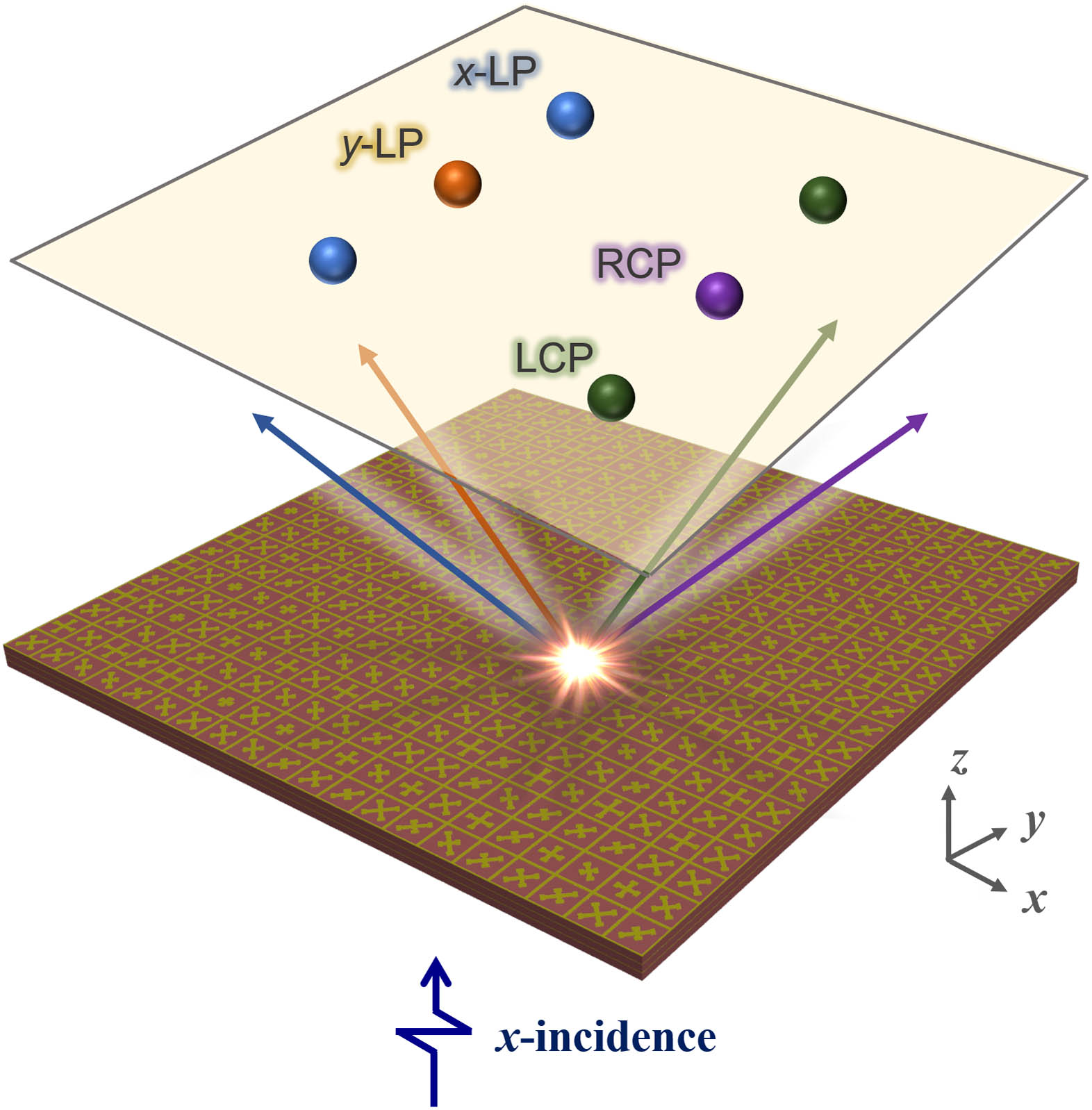
Fig. 1. Conceptual configuration of multi-focus meta-hologram with multi-channel transmission.
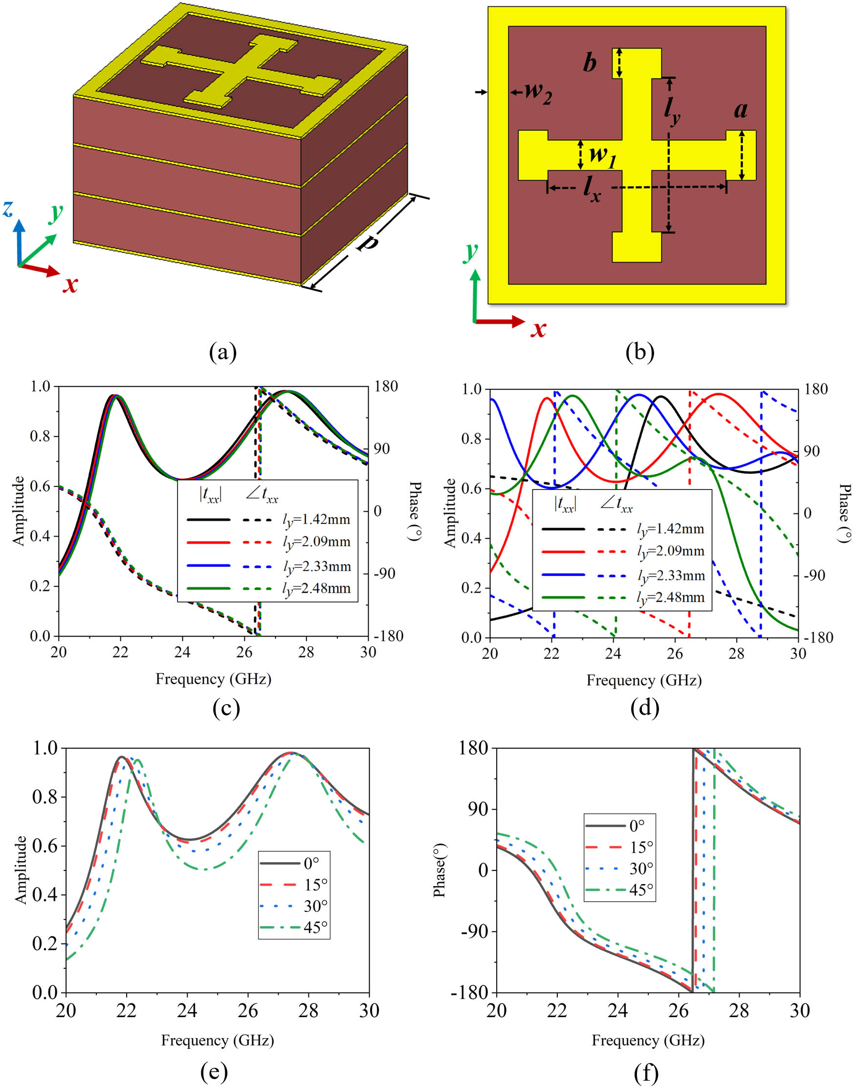
Fig. 2. (a) 3D view and (b) top view of the designed metasurface unit. Magnitude and phase spectra of the meta-atoms with different lengths l y x y l x = l y = 2.09 mm x
Fig. 3. Magnitudes and phases of the transmission coefficients obtained by 2D scanning simulation in x y
Fig. 4. (a) Top view of a part of metasurface and whole supercell. (b) Target focus image.
Fig. 5. (a)–(d) Target focus images and (e)–(h) corresponding required phase distributions for x - LP y - LP
Fig. 6. Simulated normalized magnitude distribution of (a) E x E y E l E r
Fig. 7. (a) Fabricated metasurface sample and (b) experimental setup.
Fig. 8. Measured normalized magnitude distribution of (a) E x E y E l E r
Fig. 9. Simulated and measured normalized amplitude curves of (a) E x E y E l E r
Fig. 10. Normalized magnitudes distributions of (a) theoretical, (b) simulated, and (c) measured combined electric transmitted field at 26 GHz.

Set citation alerts for the article
Please enter your email address
© Copyright 2018-2021 | Chinese Laser Press. All Rights Reserved 沪ICP备15018463号-20