
Hongfei Zang, Feng Tian, Yongjun Wang. Design of Low Crosstalk Double Coupling Ring Assisted 6-LP Fiber[J]. Chinese Journal of Lasers, 2022, 49(3): 0306002
- Chinese Journal of Lasers
- Vol. 49, Issue 3, 0306002 (2022)
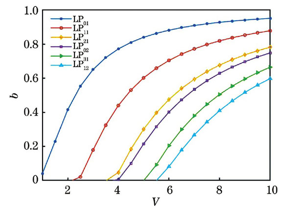
Fig. 1. V of 6-LP modes in step fiber versus b
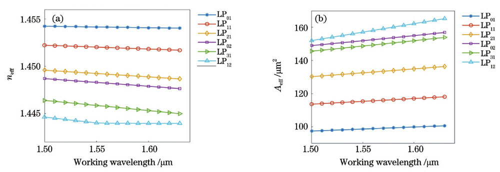
Fig. 2. Simulated results of 6-LP modes in step fiber. (a) Effective mode refractive index versus working wavelength; (b) effective mode field area versus working wavelength
Fig. 3. Mode field distributions in double coupling ring assisted few-mode fiber. (a) LP21 mode field distribution; (b) LP02 mode field distribution; (c) LP31 mode field distribution; (d) overlapping diagram of LP02 mode field and auxiliary structure of double coupling ring
Fig. 4. Schematic of refractive index distribution in auxiliary structure of double coupling ring
Fig. 5. Influences of inner circle radius of high refractive index coupling ring on effective mode refractive index and effective mode field area of LP01
Fig. 6. Influences of low refractive index coupling ring on effective mode refractive index and effective mode field area of LP01
Fig. 7. Influences of width of low refractive index coupling ring on effective mode refractive index and effective mode field area of LP01
Fig. 8. Influences of refractive index of high refractive index coupling ring on effective mode refractive index and effective mode field area of LP01
Fig. 9. Influences of width of high refractive index coupling ring on effective mode refractive index and effective mode field area
Fig. 10. Bending loss of LP01 versus working wavelength
Fig. 11. Bending loss of LP12 mode versus bending radius
Fig. 12. Comparison of effective refractive indexes of LP21 and LP02 modes in ordinary step structure and double coupling ring structure
|
Table 1. Structural parameters of 6-LP few-mode fiber
|
Table 2. Structural parameters of designed double coupling ring assisted 6-LP few-mode fiber
| ||||||||||||||||||||||||||||||||||||||||||
Table 3. Performance parameters of double coupling ring assisted 6-LP few-mode fiber at 1550 nm wavelength

Set citation alerts for the article
Please enter your email address
© Copyright 2018-2021 | Chinese Laser Press. All Rights Reserved 沪ICP备15018463号-20