• Chinese Optics Letters
  • Vol. 20, Issue 3, 031407 (2022)
Junjie Liu1、2、3, Aihua Wang1、2, Quan Sheng1、2、*, Yue Qi4, Sijia Wang5, Meng Wang1、2, Degang Xu1、2, Shijie Fu1、2, Wei Shi1、2、**, and Jianquan Yao1、2
Author Affiliations
  • 1Institute of Laser and Optoelectronics, School of Precision Instrument and Optoelectronics Engineering, Tianjin University, Tianjin 300072, China
  • 2Key Laboratory of Optoelectronic Information Science and Technology (Ministry of Education), Tianjin University, Tianjin 300072, China
  • 3Tianjin Jinhang Institute of Technical Physics, Tianjin 300308, China
  • 4Tianjin Suowei Electronic Technology Co., Ltd., Tianjin 300384, China
  • 5Qian Xuesen Laboratory of Space Technology, China Academy of Space Technology, Beijing 100094, China
  • show less
    DOI: 10.3788/COL202220.031407 Cite this Article Set citation alerts
    Junjie Liu, Aihua Wang, Quan Sheng, Yue Qi, Sijia Wang, Meng Wang, Degang Xu, Shijie Fu, Wei Shi, Jianquan Yao. Large-range alignment-free distributed-cavity laser based on an improved multi-lens retroreflector[J]. Chinese Optics Letters, 2022, 20(3): 031407 Copy Citation Text show less

    Abstract

    A multi-lens retroreflector with field curvature compensation was designed and used in an alignment-free distributed-cavity laser with a long working distance for resonant beam charging applications. The multi-lens design, which makes use of off-the-shelf components, also allows a large field of view (FoV) without requirement of large element aperture. By implementing this design, an end-pumped 1063 nm Nd:GdVO4 laser could deliver over 5 W continuous-wave output power over a large range of working distances (1–5 m) and with ±30° receiver FoV under an incident diode pump power of 16.6 W. The output power fluctuation was less than 10% when moving and tilting the receiver over such a large range, without requiring any realignment of the cavity.

    1. Introduction

    Lasers, which implement retroreflectors as opposed to conventional cavity mirrors, have the potential of being alignment-free over long working distances[14]. Such a feature makes it possible to build a distributed-cavity laser with a long working distance, which is a characteristic of great interest in applications including sensing, measurement, as well as resonant beam charging and communications[48]. Compared with the corner-cube retroreflector, the cat-eye retroreflector allows for more flexible laser designs and is more suitable for practical long distributed-cavity lasers operating in the continuous-wave (CW) scheme, which is required for applications in resonant beam charging and communications[812]. In our recent work, we presented the first experimental demonstration of efficient CW operation of such a distributed-cavity laser[13,14] with a long working distance and large field of view (FoV). We found that the cat-eye defocusing induced by spherical aberration (SA) and field curvature (FC) is the main issue that limited the working distance and the FoV of the laser. By compensating the aberrations by choosing appropriately designed elements such as a custom aspherical lens, the end-pumped Nd-vanadate lasers could deliver stable output within a working distance of 1–5 m and with a receiver FoV of ±20°, without needing to realign the cavity.

    As detailed in our former work and work by other groups, conventional cat-eye retroreflector designs typically comprise a focusing lens and a mirror positioned at its focal plane[1,8,1318]. When implemented in a distributed-cavity laser, such a cat-eye design will introduce strong SA and limit the working distance of the laser; in the case where a long focal lens is used, a large diameter output coupler is required in order to provide feedback for beams at large angle of incidence (AoI) (angle θ in Fig. 1)[13,14]. For example, in our work, in which we demonstrated a receiver FoV±20° by compensating the FC, further optimizing of the FoV was restricted by the aperture of the output coupler, even though a 50.8-mm-diameter mirror was used[14]. Therefore, in order to produce more compact lasers with larger dynamic range, the optical design needs to be improved. In this work, we designed an improved multi-lens retroreflector to remove the FoV limitation imposed by the element’s aperture. This also effectively compensated the SA and FC, enabling the distributed-cavity laser to work efficiently over a long working distance and large FoV. Here, we designed a multi-lens retroreflector consisting of off-the-shelf, standard elements; this enabled the receiver FoV to reach ±30° at a long working distance of 5 m, and the output power fluctuation was less than 10%.

    (a) Schematic of the alignment-free laser; (b) Zemax ray-trace model of the multi-lens retroreflector (the AoI interval between adjacent beams is 5°); and (c) the assembly drawing of the receiver lens tube.

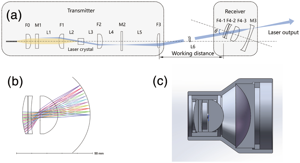
    Figure 1.(a) Schematic of the alignment-free laser; (b) Zemax ray-trace model of the multi-lens retroreflector (the AoI interval between adjacent beams is 5°); and (c) the assembly drawing of the receiver lens tube.

    2. Cavity and Optical Design

    The schematic of the alignment-free distributed-cavity laser is shown in Fig. 1(a). The details of the transmitter (from the fiber-coupled diode pump to the intracavity lens F3) can be found in our prior work[14]. The maximum 808 nm diode pump power used to end-pump the 1063 nm Nd:GdVO4 laser was 16.6 W. To optimize the alignment-free range of the laser, we designed an improved receiver retroreflector, which comprised of three lenses and a partially reflective mirror (output coupler), instead of the conventional two-element cat-eye design. The lens F4-1 was a plano-convex lens with an effective focal length (EFL) of 76 mm, while the lenses F4-2 and F4-3 were plano-concave and plano-convex, with EFLs of 160mm and 25.4 mm, respectively. The output coupler M3 was plano-concave with a radius of curvature (ROC) of 32.5 mm.

    The distances between the four elements above (referred to as L7-1, L7-2, and L7-3) were 0.1 mm, 5.9 mm, and 21 mm, respectively.

    The parameters of the lenses and mirror used to make up the retroreflector were optimized to provide good retroreflection for incident beams across a large FoV of ±30°. The requirements of “good retroreflection” here include the direction, path, as well as the divergence of the back reflected beam, to be opposite to those of the incident beam. The availability of the elements was also considered during the design, i.e., the standard off-the-shelf elements were preferred. All the lenses in the laser cavity were constructed from N-BK7 and were antireflective (AR) coated at 1064 nm (R<0.2%). The reflectivities of mirrors M2 and M3 at the 1063 nm laser wavelength were 30% and 50%, respectively, with a corresponding “effective feedback” of 82% (18% output coupling). The specifications of each element and the distances between them are summarized in Table 1. The length of the retroreflector (from the convex face of F4-1 to the plano face of M3) was less than 45 mm. Figure 1(b) shows the ray-tracing model of this multi-lens retroreflector implemented through Zemax software. The AoI interval between each beam is 5°, and the 50.8 mm diameter of output coupler M3 supports a large AoI of ±45° (the 25.4 mm aperture of the lens F4-1 is insufficient for a 4-mm-wide incident beam with ±50° AoI). We also made a lens tube to mount the elements together as an assembly, the schematic of which is shown in Fig. 1(c). It should be mentioned that we originally planned to use one convex-concave lens instead of using two lenses F4-1 and F4-2, two make a three-element device. However, after inquiring with several suppliers, we were unable to source the appropriate elements in stock, and we proceeded with the design as outlined above; in this case, all three lenses with AR coatings at the laser wavelength were in stock with suppliers. The improved retroreflector making use of off-the-shelf elements is hence very cost-effective.

    OpticShapeEFL/ROC (mm)Diameter (mm)Distance/Spacing (mm)
    F4-1Plano-convex76.0/39.2825.0L71:0.1
    F4-2Plano-concave−160.0/−82.6225.0L72:5.9
    F4-3Plano-convex25.4/13.0825.0L73:21
    M3Plano-concave−63.0/−32.550.0

    Table 1. The Elements Used in the Multi-Lens Retroreflector

    As illustrated in our former work, the SA and FC are the main issues that limit the working distance and the FoV, respectively[13,14]. Using ABCD matrices, we know the fundamental mode has a beam diameter of 4mm when it reaches the receiver (lens F4-1) at the longest working distance in the experiment of 5 m. Using Zemax software, we found that most of the beam energy is within the Airy radius after being focused on the output coupler M3, which means that the beam is near-diffraction-limited and would not be influenced much by the SA. In terms of FC, Fig. 2 shows the calculated FC as a function of AoI of the multi-lens retroreflector (black solid line) using Zemax software. It can be seen that the absolute value of FC within the AoI of ±30° was below 0.04 mm, and this increased to 0.22 mm at an AoI of ±40°. For cat-eye retroreflectors, which use lenses with different focal lengths, it is unreasonable to compare their aberration-induced defocusing in terms of distance (millimeters) directly. For instance, with the same aberration-induced defocusing of 1 mm, a cat-eye retroreflector with a short focal length lens would cause more significant distortion of the beam after retroreflection than a retroreflector with a long focal length lens. A more reasonable way to quantify the aberration-induced defocusing is to use the focusing power (in terms of diopters). A defocused retroreflector would focus or defocus the incident beam, which means that the beam reflected back along the incident path has a divergence different from that of the incident beam. It is easy to understand that the same focusing/defocusing has the same influence on the laser operation (at the same working distance). The FC-induced defocusing in terms of diopters is also plotted in Fig. 2, using the blue dashed line. The maximum absolute value of calculated defocusing within the optimized FoV of 30° is no more than 0.11 D (at ±20°), and this increased to 0.31 D and 0.87 D at the AoIs of 35° and 40°, respectively. For comparison, we also converted the calculated defocusing in terms of millimeters in Fig. 3 of Ref. [14] into diopters. For the FC-compensated cat-eyes #3 and #4, the maximum absolute values of FC-induced defocusing within the aperture-limited FoV were 0.13 D and 0.15 D, respectively; also, the laser output power did not exhibit an obvious decrease in these cases. These values can be used to estimate if the FC is compensated well to facilitate efficient laser output over the desired FoV. The FC of our multi-lens receiver is below 0.11 D with an FoV of ±30°, lower than the values stated above. Therefore, we can expect that the output power will be stable across this range, but will decrease if the AoI increases.

    Calculated FC-induced defocusing in terms of millimeters and diopters.

    Figure 2.Calculated FC-induced defocusing in terms of millimeters and diopters.

    Power transfer of the laser at the working distances of 2 m and 5 m (AoI = 0°). The lines are a guide to the eye.

    Figure 3.Power transfer of the laser at the working distances of 2 m and 5 m (AoI = 0°). The lines are a guide to the eye.

    3. Results and Discussion

    We first characterized the laser output power at an AoI of 0°, i.e., the transmitter and receiver were parallel with one another and shared a common optical axis. The results are plotted in Fig. 3. The laser threshold was 3W incident diode pump power, and the maximum output powers at the working distances of 2 m and 5 m were 5.80 W and 5.13 W, respectively, with the receiver optimized at each working distance. The output powers were similar to those obtained with conventional two-element cat-eye retroreflectors, as detailed in our former work[14]; this reveals that using two additional lenses in the cavity does not add significant insertion loss.

    Figure 4 shows the laser output power as a function of working distance L6. The solid circle shows the results with the distance L7-3 unchanged after first being optimized at the longest working distance of 5 m. Here, moderate fluctuation in power between 5.03 W and 5.55 W is observed when the working distance L6 was shortened from 5 m to 1 m. The “alignment-free” output powers were a little lower than that obtained when the distance L7-3 was optimized at each working distance (empty square). However, for practical resonant beam charging and communications applications, it is generally considered impossible to reoptimize the laser, as the position of the receiver changes. Therefore, stable “alignment-free” output can be considered a more important characteristic for these lasers to have.

    Laser output power as a function of working distance L6 under an incident pump power of 16.6 W, with the receiver optimized at the working distance 5 m and with the receiver optimized at each point. The lines are a guide to the eye.

    Figure 4.Laser output power as a function of working distance L6 under an incident pump power of 16.6 W, with the receiver optimized at the working distance 5 m and with the receiver optimized at each point. The lines are a guide to the eye.

    The receiver FoV (θ) was characterized with the multi-lens retroreflector on the optical axis of the transmitter under the maximum pump power of 16.6 W. Since the FC was compensated, a large receiver FoV was achieved, as plotted in Fig. 5. At the longest working distance of 5 m, the laser output was above 5 W within the optimized FoV of ±30°, with a very small fluctuation between 5.17 W and 5.05 W. When further increasing the AoI to ±35°, the output power decreased significantly to 2.5W, and no laser output was observed at AoI of ±40°. When the working distance L6 was decreased to 2 m, the wider stability zone made it more resistant to FC-induced defocusing. At the AoIs of ±35° and ±40°, over 4 W and 2W laser output powers were obtained, respectively. To the best of our knowledge, this is the largest FoV for such an alignment-free laser in the CW scheme, and this performance is attributed to careful and innovative optical design. When the elements were mounted in the lens tube, the maximum FoV reduced to ±30° because the output beam was clipped by the lens tube at a larger AoI. As shown in Fig. 1(c), the mirror M3 was not positioned at that rear end of the lens tube, as we planned to add another lens there to refocus the output beam to a photovoltaic cell (as a demonstration of resonant laser charging application). The large alignment-free range of this distributed-cavity laser (which includes both the working distance and FoV) paves the way for practical implementations of resonant beam charging applications.

    Receiver FoV measured at a working distance of 2 m and 5 m (with an incident pump power of 16.6 W). The lines are a guide to the eye.

    Figure 5.Receiver FoV measured at a working distance of 2 m and 5 m (with an incident pump power of 16.6 W). The lines are a guide to the eye.

    4. Conclusions

    In this work, we designed an improved multi-lens retroreflector and used it in a distributed-cavity, alignment-free laser for resonant beam charging applications. The retroreflector, which was composed of off-the-shelf elements, was designed with a large aperture-limited FoV and with SA and FC compensated so that the distributed-cavity laser could operate efficiently over a long working distance and FoV. Using the improved multi-lens retroreflector as the receiver, the laser output power fluctuation was below 10%, with the receiver moving across a working distance of 1–5 m and tilted over a large FoV of ±30°. These results are a significant improvement over conventional two-element cat-eye retroreflectors with similar physical length and aperture. Our design extends the dynamic range of distributed-cavity alignment-free lasers significantly and is promising for laser resonators and optical systems that require effective retroreflection over a large FoV.

    References

    [1] B. Singh, S. R. Daultabad, V. V. Subramaniam, A. Chakraborty. Performance of an 80 W copper vapor laser with “alignment free” unstable CAT-EYE resonator and other configurations using intra-cavity apertures. Opt. Commun., 281, 6080(2008).

    [2] P. Tripathi, R. Lovberg. A 700 meter long mode-locked argon ion laser. IEEE J. Quantum Electron., 11, 881(1975).

    [3] G. Linford, E. Peressini, W. Sooy, M. Spaeth. Very long lasers. Appl. Opt., 13, 379(1974).

    [4] Y. Wang, T. Dai, X. Liu, Y. Ju, B. Yao. Dual-wavelength injection-seeded Q-switched Ho:YLF laser for CO2 differential absorption lidar application. Opt. Lett., 44, 6049(2019).

    [5] E. Mehdizadeh, J. Lunine, G. Atkinson. Intracavity laser spectroscopy with an ion-doped, solid-state Tm3+:YAG laser. J. Quant. Spectrosc. Radiat. Transf., 68, 453(2001).

    [6] Q. Zhang, W. Fang, Q. Liu, J. Wu, P. Xia, L. Yang. Distributed laser charging: a wireless power transfer approach. IEEE Internet Things J., 5, 3853(2018).

    [7] J. Lim, T. S. Khwaja, J. Ha. Wireless optical power transfer system by spatial wavelength division and distributed laser cavity resonance. Opt. Express, 27, A924(2019).

    [8] M. Xiong, M. Liu, Q. Jiang, J. Zhou, Q. Liu, H. Deng. Retro-reflective beam communications with spatially separated laser resonator. IEEE Trans. Wirel. Commun., 20, 4917(2021).

    [9] G. Zhou, A. Alfrey, L. Casperson. Modes of a laser resonator with a retroreflecting corner cube mirror. Appl. Opt., 21, 1670(1982).

    [10] Y. Tan, S. Zhang. Alignment-free He–Ne laser with folded cavity. Opt. Lasers Eng., 46, 578(2008).

    [11] R. Della-Pergola, O. Aplert, O. Nahmias, V. Vaisleib. Spatially distributed laser resonator. U.S. patent(2017).

    [12] O. Aplert, E. Ronen, O. Nahmias, O. R. Mor, L. Golan, R. Sagi. Distributed coupled resonator cavity. U.S. patent(2019).

    [13] Q. Sheng, M. Wang, H. Ma, Y. Qi, J. Liu, D. Xu, W. Shi, J. Yao. Continuous-wave long-distributed-cavity laser using cat-eye retroreflectors. Opt. Express, 29, 34269(2021).

    [14] Q. Sheng, M. Wang, H. Ma, Y. Qi, J. Liu, D. Xu, W. Shi, J. Yao. Enhancing the field of view of a distributed-cavity laser incorporating cat-eye optics by compensating the field-curvature. Opt. Laser Technol., 151, 108011(2022).

    [15] B. Fermigier, G. Lucas-Leclin, J. Dupont, F. Plumelle, M. Houssin. Self-aligned external-cavity semiconductor lasers for high resolution spectroscopy. Opt. Commun., 153, 73(1998).

    [16] Z. Xu, S. Zhang, W. Du, Y. Li. Misalignment sensitivity of the cat’s eye cavity He–Ne laser. Opt. Commun., 265, 270(2006).

    [17] Z. Xu, S. Zhang, Y. Li, W. Du. Adjustment-free cat’s eye cavity He–Ne laser and its outstanding stability. Opt. Express, 13, 5565(2005).

    [18] W. Wang, Y. Gao, D. Sun, X. Du, J. Guo, X. Liang. Adjustable-free and movable Nd:YVO4 thin disk laser based on the telecentric cat’s eye cavity. Chin. Opt. Lett., 19, 111403(2021).

    Junjie Liu, Aihua Wang, Quan Sheng, Yue Qi, Sijia Wang, Meng Wang, Degang Xu, Shijie Fu, Wei Shi, Jianquan Yao. Large-range alignment-free distributed-cavity laser based on an improved multi-lens retroreflector[J]. Chinese Optics Letters, 2022, 20(3): 031407
    Download Citation