Key Laboratory of Space Laser Communication and Detection Technology, Shanghai Institute of Optics and Fine Mechanics, Chinese Academy of Sciences, Shanghai 201800, China
A scanning three-dimensional coherent laser radar (ladar) based on the frequency modulated continuous wave (FMCW) is proposed and demonstrated, which can obtain many three-dimensional high-quality images. The system utilizes an electro-optic modulator and an optical filter to output a linear FMCW with a bandwidth of 2 GHz. The flexible and variable rotating double prism is used for beam scanning. The images of flight demonstration are formed by attitude compensation correction. The experiment result validates the performance of our system for airborne three-dimensional scanning imaging.
Laser radar (ladar) has large technology advantages on distinguishing, classifying, and acquiring targets. Many countries spent a lot of manpower and financial resources to research ladar technology, and various three-dimensional (3D) ladars are developed[1–4]. They are usually divided into the intensity direct-detection type and the heterodyne detection type. The former is using incoherent pulse light and detecting the target echo intensity with the photodetector directly. The typical incoherent 3D ladar is based on the time of flight (TOF) method[5,6]. Many fields, like an unmanned aerial vehicle and automatic drive, have launched many types of products[7]. This technology is simple and mature. However, the following problems still exist: (1) anti-jamming problems, susceptible to ambient light interference and interference between ladars; (2) detection distance problems, low detection sensitivity and long-range detection requiring a large transmitting power; (3) scanning problems, poor compatibility with optical phased array (OPA) solid-state scanning, seriously affecting the detection distance. However, the coherent heterodyne detection type has many advantages, which can suppress background noise, has strong anti-jamming ability, can effectively improve the signal-to-noise ratio (SNR), and can obtain multidimensional information, including distance, speed, polarization, etc. In recent years, it has been extensively researched and applied in the field of target detection, recognition and imaging, such as synthetic aperture ladar (laser SAR)[8–10] and coherent ranging velocimetry lidar[11].
In recent years, a 3D coherent lidar based on pseudo-random coding is implemented for 500 m distance outdoor imaging[12]. In addition, ladar based on the frequency modulated continuous wave (FMCW) is widely used for distance measurement[13–15]. Pearson et al.[16] use the sawtooth-like FMCW to realize outdoor 3D coherent laser imaging. However, most of the experiments introduced above are conducted in the laboratory with a stable optical table and close distance. These experiments are basically carried out under ideal conditions with static objectives. The short-range and static experiments do not raise high requirements for the laser coherence. Therefore, there are more challenges needing to be explored and resolved in real environments on airborne coherent scanning imaging. They include the high coherence requirement of the laser source from long-distance detection, and the attitude compensation imaging algorithm for airborne unstable platform motion. Although many lidar transmitters use an electro-optic in-phase/quadrature (I/Q) modulator to realize carrier-suppressed complex optical field modulation[17], its implementation is relatively complex.
In this Letter, we present an airborne coherent 3D ladar system based on FMCW. The system uses an electro-optical modulator and an optical filter to achieve a large bandwidth and high-quality laser. The rotating prism scanner is used for two-dimensional space scanning with different patterns, which is more reliable and flexible than the one-dimensional common mechanical scanner. The 3D imaging experiment outdoors and airborne platform at 900 m is conducted to validate the effectiveness of the system. Attitude data, which is collected by an inertial navigation system (INS) in the airborne experiment, is used to correct the platform attitude errors.
Sign up for Chinese Optics Letters TOC. Get the latest issue of Chinese Optics Letters delivered right to you!Sign up now
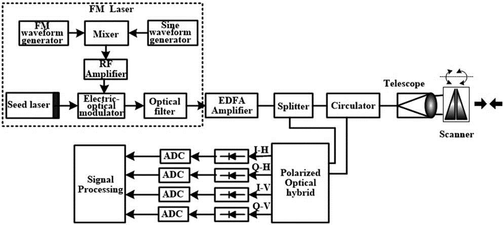
The setup of the 3D coherent ladar system is shown in Fig. 1. The system consists of the FM laser, erbium-doped fiber amplifier (EDFA), transmitter and receiver, optical scanner, polarized optical hybrid, analog-to-digital converter (ADC), and signal processing modular. The FM laser is generated by an electro-optical modulator and an optical filter. The electric-optical modulator is modulated by the radio frequency (RF) amplifier signal, which is a mixing signal of the sine baseband signal and the linear FM signal, and the bandwidth of the modulated laser signal is 2 GHz, corresponding to 7.5 cm resolution. The EDFA is used to amplify the laser power. The power of the transmitted signal is 1.8 W with a 50 mm emitting/receiving aperture. A rotation double prism for the optical scanner is used to control the beam scanning. The transmitter and receiver module consist of a splitter, circulator, and telescope, and this is a common transmitter and receiver optical path structure. The FM laser signal amplified by the EDFA is divided into two parts by the splitter. One enters into the transceiver chain to illuminate the target and receive the diffused echo, and the other goes into the polarized optical hybrid as the local oscillator (LO). The echo is divided into polarized orthogonal beams and amplified through heterodyne receiving with the LO, respectively. Balanced photodetectors and high-speed ADCs are utilized to obtain the real digital signals. Further data processing could obtain distance and velocity information of the target.
Figure 1.Block diagram of the proposed linear FMCW ladar system.
The laser seed source of the above system is a low noise laser with a wavelength of 1550.148 nm. The phase modulator is a lithium niobate electro-optic modulator with a bandwidth of 10 GHz, and the optical filters are thermally tunable fiber Bragg grating (FBG) filters with an annulus. The tunable central wavelength ranges from 1549.8 to 1550.12 nm. In addition, the linear FM generator, EDFA, coherent optical receiver, and double prism scanner are homemade.
In this Letter, we propose to utilize an electro-optical modulator and an optical filter to produce a linear FMCW laser signal. The driving signal of the electro-optic modulator is the mixing of the sine RF signal and the FM signal. As illustrated in Fig. 1, the output optical field of the laser can be expressed as where is the electric field intensity, is the carrier frequency of the seed laser, is the modulated phase of the electric-optic modulator, and is the initial phase.
The driving signal of the electro-optic modulator is the mixing of the sinusoidal RF signal and the FM signal. It can be written as where is the sine RF signal amplitude, is the frequency of the sinusoidal RF signal, is the linear FM signal amplitude, is the low cutoff frequency of the FM signal, is the high cutoff frequency of the FM signal, and t is the linear frequency modulation time. The above voltage is used to modulate the electro-optical phase, where the parameter is used to control the starting chirp frequency and make the optical signal be filtered effectively. After modulation, the output optical signal can be expressed as where , and is the half-wave voltage of the electro-optical phase modulator. We do a Bessel function expansion for the above exponential function. The function can be written as where is the first kind of Bessel function of the th order, is the modulation index, the first term on the right side is the carrier term, the second is the lower sideband term, and the last is the upper sideband term.
Then, the output signal from the electro-optical phase modulator is filtered by the optical filter. So, the output signal from the optical filter is the required order sideband signal. In this Letter, the second-order sideband signal is used, and the other-order sideband signal is filtered out. When , the output signal can be obtained as
The frequency spectrum of the RF signal driving the electro-optic modulator is 4.7 to 5.7 GHz, as shown in Fig. 2(a). Figure 2(b) is the frequency noise spectrum and linewidth of the linear FM laser. Among them, the blue curve is the frequency noise spectrum, and the green line is the condyle-dividing line. According to Domenico’s algorithm, the integral linewidth corresponding to different observation times can be calculated by the frequency noise spectrum. The result is the green discrete point in Fig. 2(b). From Fig. 2(b), the linewidth of the laser is about 8 kHz. The frequency noise spectrum is measured by a laser noise tester. The measurement principle is described in Ref. [18].
Figure 2.(a) Frequency spectrum for signal driving the electro-optic modulator and (b) frequency noise spectrum and linewidth of the linear FM laser.
For the 3D coherent ladar system based on FMCW technology, the core content is the range measurement by coherent detection. The coherent detection is realized by a polarized optical hybrid, and the return and local beams are mixed by the polarized optical hybrid[19,20] and the balance detector to obtain the heterodyne signal. By use of an optical hybrid[19,20], the optical phase difference between the two beams can be detected as the real and imaginary parts of a phase complex exponential. In the following digital processing, the phase complex exponential can be easily evaluated by where is the time of the laser flight time, and the time is related to target distance and velocity. Therefore, the up-ramp frequency can be written as where is the modulated bandwidth of the FM laser, is the speed of light, is the speed of the moving target, and is the distance between the ladar and target. In practical applications, there are many kinds of modulated transmitting waveforms to realize distance measurement, such as triangular modulation[11,17], isosceles trapezoid modulation[21], and right angle trapezoidal modulation. The isosceles trapezoid waveform consists of three segments: up-ramp chirp, down-ramp chirp, and constant frequency. The three segments information, which is redundant, can also be used to obtain an accurate moving target distance and speed. We use the isosceles trapezoid modulated waveform in our experiment, and the down-ramp frequency can be written as
The final target distance is
The other two-dimensional coordinates of the 3D information are generated by an optical scanner, including electro-optical scanner, acousto-optic scanner, liquid crystal display (LCD) scanner, universal rack scanner, rotation double prism scanner, and so on. The electro-optical scanner, acousto-optic scanner, and LCD scanner are not a wavefront reproduced scanner, and they will reduce the beam transmittance, so they are not suitable for applications with high wavefront and high energy requirements. The universal rack scanner is generally large in size and weight, and its disadvantage is poor dynamic performance. It is difficult to achieve high-precision beam scanning. The rotating double prism scanner[22] has a stable mechanical structure and can achieve high scanning precision and small space occupation. Scanning anywhere in a specific cone can be achieved by simply and flexibly controlling the angle of rotation of the two prisms.
In practical applications, the beam scanning range within the time of laser flight cannot exceed the received field of view (FOV). Therefore, when the received FOV and the working distance are constant, the range of the beam scanning area must be adjusted to match the contradiction between the scanning speed and the angle of view. Rotating double prisms only requires a simple control of the speed and relative angular difference between the two rotating prisms to achieve a flexible scanning area. It is very convenient for different occasions.
The airborne 3D scanning coherent ladar is affected by the attitude of the airborne platform. In order to improve the accuracy of the 3D terrain elevation, the real-time attitude data is collected by an INS, including pitch angles, roll angles, heading angles, and the global positioning system (GPS) position information (longitude, latitude, altitude) of the platform. The processing of airborne ladar is as follows. The laser scanning instantaneous coordinate system is generally used. When the distance between the laser beam and target at a certain instant is , the coordinates of the beam in the instantaneous laser beam coordinate system are . It can be written as
The laser scanning coordinate system is used to describe the scanning of the rotating double prisms. Three attitude angles [roll angle (), pitch angle (), and heading angle () of the aircraft platform] are measured by the INS. Generally, the inertial platform reference coordinate system is adopted. Furthermore, it is transformed into a horizontal reference coordinate system. The coordinates in the horizontal reference frame are :
Then, the coordinate is further transformed into the local vertical reference coordinate system, the World Geodetic System-84 (WGS-84) coordinate system . The block diagram of coordinate transformation is shown in Fig. 3. Finally, the 3D coordinates of the terrain elevation can be obtained as follows:
In the above formula, is the radius of curvature of the ellipsoid prime vertical circle. is the radius of the ellipsoid length. is the first eccentricity of the ellipsoid. , , are the longitude, latitude, and height of the aircraft, respectively.
The following content is the verification test of the coherent ladar system. Firstly, we estimate the sensitivity, range accuracy, and resolution of the ladar received system. Fiber extensions and attenuators are used to obtain tunable power of the optical signal and carry out heterodyne detection with a 2 mW LO. The extended fiber distance is 1478.84 m. The coherent signal is collected for 4000 times each time, and the probability of detection is counted. The relationship between the signal power and the SNR is shown in Fig. 4(a). When the SNR reaches 10 dB or more, the detection probability reaches 100%, and the echo power at this time is about 1 pW. The detection accuracy measured by the experiment reaches 0.1 m.
Figure 4.(a) Relationship between the signal power and the SNR and (b) result of the frequency resolution measurement.
Then, the Fourier transform is performed on the coherent detection signal with a received power of 0.6 pW, and a 3 dB signal resolution of 5 kHz is obtained. The corresponding chirp time is 1/3 ms. The modulation bandwidth is 2 GHz. So, the actual resolution is 0.125 m. The processing result is as shown in Fig. 4(b).
Then, in order to demonstrate the ability of the 3D coherent ladar system, we carried out the 3D imaging experiment outdoors. The laser emitter of the system includes a rotation double prism, as shown in Fig. 5(a). The optical aperture is 50 mm. The max scanning angle of the rotating double prism is 50°, and the different speed ratios of the two rotating double prisms can be controlled to realize different scanning patterns. The scanning speed ratio of the two prisms is 720:1 in experiment, and the scanning pattern is as shown in Fig. 5(b). The distance of the target is 100 m to 1 km. Figure 6(a) shows the real photo of the outdoor target scene, where the maximum distance is up to 1 km. The scanning time is 6 min. The angular resolutions in the azimuth and elevation directions are about 31 μrad. The distance of the tallest building on the picture is about 500 m, and the target scene contains a lot of buildings and trees. Figure 6(b) shows the 3D point cloud image using the coherent ladar system, and the number of the point cloud is 360,000. From Fig. 6(b), the buildings and trees from different distances are rebuilt clearly. These imaging results were obtained in the morning of a clear day in late June 2018. The optical collimator is facing the sun. The background light from the sun is quite strong. This shows that the coherent ladar has the largest advantage of anti-interference from the background light.
Figure 5.(a) Rotating double prisms and (b) its scanning pattern in experiment with 1 km distance.
In the above-mentioned outdoor 3D coherent ladar imaging experiment, the feasibility of the 3D coherent imaging is verified. The ladar system is stationary.
Afterward, we carried out an airborne flight experiment with flight height of 900 m. The flight path of the aircraft is a circular track of several kilometers, over the ground of natural buildings, lakes, hills, etc. The 3D coherent ladar system is installed on the Y-5 aircraft, as shown in Fig. 7. Figure 7(a) shows the aircraft in flight, and Fig. 7(b) shows the coherent ladar system installed in the cabin. The 3D coherent ladar is installed in the belly position, and the beam is perpendicular to the bottom of the cabin to illuminate the ground target. During the experiment, the flight speed of the aircraft is about 50 m/s. Meanwhile, the scanning pattern of the rotating double prism that was used is circular.
Figure 7.Installed 3D coherent ladar system. (a) Flighting Y-5 aircraft and (b) the installed system viewed from inside.
Figure 8 shows the satellite image, and the yellow marker is the flight trajectory. The airborne scanning angle in the experiment is 4°, and the speed ratio of 1:1 is used for the rotating double prism. So the narrow band along the flight path is scanned and imaged. There are high-rise buildings, rivers, bridges, hills, etc. Figure 9 is part of the imaging results of the airborne ladar flying along the narrow band. Figure 9(a) shows the satellite picture (left) and imaging results (right) with two large spherical buildings and a tower. Figure 9(b) is a row of continuous square buildings (left) and imaging results (right). The scanning time of the two images is about 4 s, and the number of the point cloud is 4000.
Figure 8.Satellite image of the flight trajectory.
The airborne 3D coherent ladar based on the broadband linear FMCW technology and rotational double prism scanning and the corresponding 3D imaging results are reported in the Letter. The system utilizes an electro-optic modulator and an optical filter to achieve linear FMCW with 2 GHz bandwidth. A set of rotational double prisms is used to obtain the reliable, flexible, and convenient beam scanning. The attitude data is collected and corrected to reconstruct high-resolution images for the long-distance airborne 3D coherent ladar. The image results verify the feasibility of the system. This 3D coherent ladar system uses 1 kHz pulse repetition frequency (PRF) and polarized optical hybrid. The point clouds are relatively sparse. In the next stage, we will study the imaging of the dual polarization imaging and further improve the PRF.