Author Affiliations
1School of Mechanical Engineering, Shanghai Jiao Tong University, Shanghai 200030, China2China Nuclear Power Technology Research Institute, Shenzhen 518000, Chinashow less
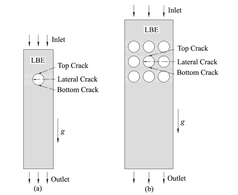
Fig. 1. Diagram of geometric model in computational domain (a) Single tube, (b) 3×3 tube bundle
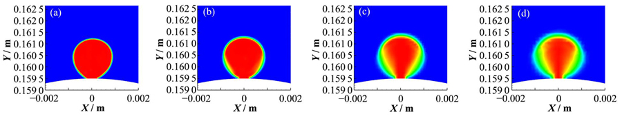
Fig. 2. Effect of grid size on bubble shape (a) 0.025 mm, (b) 0.050 mm, (c) 0.100 mm, (d) 0.150 mm
Fig. 3. Velocity cloud for 0.25 m·s-1 inlet velocity of LBE (a) Single pipe, geometry size: 200 mm×50 mm, (b) 3×3 tube bundle, geometry size: 250 mm×81 mm
Fig. 4. The process of bubble growth and detachment under steam seepage
Fig. 5. Influence of contact angle on steam bubble growth and detachment at top crack
Fig. 6. Influence of contact angle on steam bubble growth and detachment at lateral crack
Fig. 7. Influence of contact angle on steam bubble growth and detachment at bottom crack
Fig. 8. The process of bubble growth and detachment under low steam jet velocity
Fig. 9. Effect of increasing steam flow
Fig. 10. Effect of increase the flow rate of LBE descending flow field
Fig. 11. The accumulation of steam bubbles in 3×3 tube bundle flow field
参数 Parameters | 单管计算域几何 Single-tube computational domain geometry | 3×3管束计算域几何 3×3 bundle computational domain geometry |
---|
计算域宽度 Width of computational domain / mm | 50 | 81 | 计算域长度 Length of computational domain / mm | 200 | 250 | 传热管外径 External diameter of tubes / mm | 19 | 19 | 裂纹管中心到出口距离 Distance from cracked tube center to outlet / mm | 150 | 180 | 轴向管中心距 Axial tube center distance / mm | — | 25 | 径向管中心距 Radial tube center distance / mm | — | 25 |
|
Table 1. Geometry parameters of computational domain
物质 Material | 密度 Density / kg·m-3 | 动力粘度 Dynamic viscosity / N·s·m-2 | 表面张力 Surface tension / N·m-1 |
---|
LBE | 10 347.379 | 1.904×10⁻³ | 0.399 | 蒸汽 Vapor | 0.379 | 2.029×10⁻⁵ | — |
|
Table 2. Properties of LBE and vapor
算例 Cases | LBE入口速度 Inlet velocity of LBE / m·s-1 | 裂纹位置 Location of cracks | LBE与传热管表面接触角 Contact Angle between LBE with tube surface / (°) | 蒸汽入口速度 Inlet velocity of vapor / m·s-1 |
---|
1 | 0.25 | 顶部裂纹 Top crack | 5.4 | 0.02 | 渗流射流蒸汽 Low-speed steam jet | 2 | 0.25 | 顶部裂纹 Top crack | 50 | 0.02 | 3 | 0.25 | 顶部裂纹 Top crack | 90 | 0.02 | 4 | 0.25 | 顶部裂纹 Top crack | 130 | 0.02 | 5 | 0.25 | 水平裂纹 Lateral crack | 5.4 | 0.02 | 6 | 0.25 | 水平裂纹 Lateral crack | 50 | 0.02 | 7 | 0.25 | 水平裂纹 Lateral crack | 90 | 0.02 | 8 | 0.25 | 水平裂纹 Lateral crack | 130 | 0.02 | 9 | 0.25 | 底部裂纹 Bottom crack | 5.4 | 0.02 | 10 | 0.25 | 底部裂纹 Bottom crack | 50 | 0.02 | 11 | 0.25 | 底部裂纹 Bottom crack | 90 | 0.02 | 12 | 0.25 | 底部裂纹 Bottom crack | 130 | 0.02 | 13 | 0.25 | 顶部裂纹 Top crack | 5.4 | 0.5 | 低速射流蒸汽 Low-speed steam jet | 14 | 0.25 | 水平裂纹 Lateral crack | 5.4 | 0.5 | 15 | 0.25 | 底部裂纹 Bottom crack | 5.4 | 0.5 | 16 | 0.25 | 顶部裂纹 Top crack | 5.4 | 1 | 17 | 0.25 | 水平裂纹 Lateral crack | 5.4 | 1 | 18 | 0.25 | 底部裂纹 Bottom crack | 5.4 | 1 | 19 | 0.5 | 顶部裂纹 Top crack | 5.4 | 0.5 | 20 | 0.5 | 水平裂纹 Lateral crack | 5.4 | 0.5 | 21 | 0.5 | 底部裂纹 Bottom crack | 5.4 | 0.5 |
|
Table 3. Boundary conditions of single heat transfer tube under crack condition
算例Cases | LBE入口速度 Inlet velocity of LBE / m·s-1 | 裂纹位置 Location of cracks | LBE与传热管表面接触角 Contact angle between LBE with tube surface / (°) | 蒸汽入口速度 Inlet velocity of vapor / m·s-1 |
---|
22 | 0.25 | 顶部裂纹 Top crack | 5.4 | 0.5 | 低速射流蒸汽 Low-speed steam jet | 23 | 0.25 | 水平裂纹 Lateral crack | 5.4 | 0.5 | 24 | 0.25 | 底部裂纹 Bottom crack | 5.4 | 0.5 |
|
Table 4. Boundary conditions of 3×3 tube bundle cracking