• Acta Physica Sinica
  • Vol. 68, Issue 19, 195204-1 (2019)
Sui-Han Cui1, Zhong-Zhen Wu1、2、*, Shu Xiao1, Lei Chen1, Ti-Jun Li1, Liang-Liang Liu1, K Y Fu Ricky2, Xiu-Bo Tian1, K Chu Paul2, and Wen-Chang Tan1
Author Affiliations
  • 1School of Advanced Materials, Peking University Shenzhen Graduate School, Shenzhen 518055, China
  • 2Department of Physics and Materials Science, City University of Hong Kong, Hong Kong 999077, China
  • show less
    DOI: 10.7498/aps.68.20190583 Cite this Article
    Sui-Han Cui, Zhong-Zhen Wu, Shu Xiao, Lei Chen, Ti-Jun Li, Liang-Liang Liu, K Y Fu Ricky, Xiu-Bo Tian, K Chu Paul, Wen-Chang Tan. Simulation study on plasma discharge and transport in cylindrical cathode controlled by expanding electromagnetic field[J]. Acta Physica Sinica, 2019, 68(19): 195204-1 Copy Citation Text show less
    Schematic diagram of the cylindrical cathode and the electromagnetic coils.筒形阴极及电磁线圈结构示意图
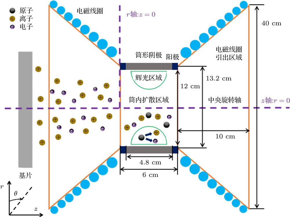
    Fig. 1. Schematic diagram of the cylindrical cathode and the electromagnetic coils.筒形阴极及电磁线圈结构示意图
    The distribution of the magnetic induction line vs. the current in electromagnetic coils: (a) 0 A; (b) 5 A; (c) 10 A; (d) 15 A; (e) –5 A; (f) –10 A and (g) –15 A. The purple dotted line is the center axis of the cylindrical cathode and the magnified area of the cylindrical cathode is marked by the blue square.磁感线分布与电磁线圈电流的关系, 右侧为筒形阴极内的磁感线分布放大图 (a) 0 A; (b) 5 A; (c) 10 A; (d) 15 A; (e) –5 A; (f) –10 A; (g) –15 A. 图中紫色虚线为筒形阴极中央轴, 蓝色方框中的部分为筒形阴极的放大区域
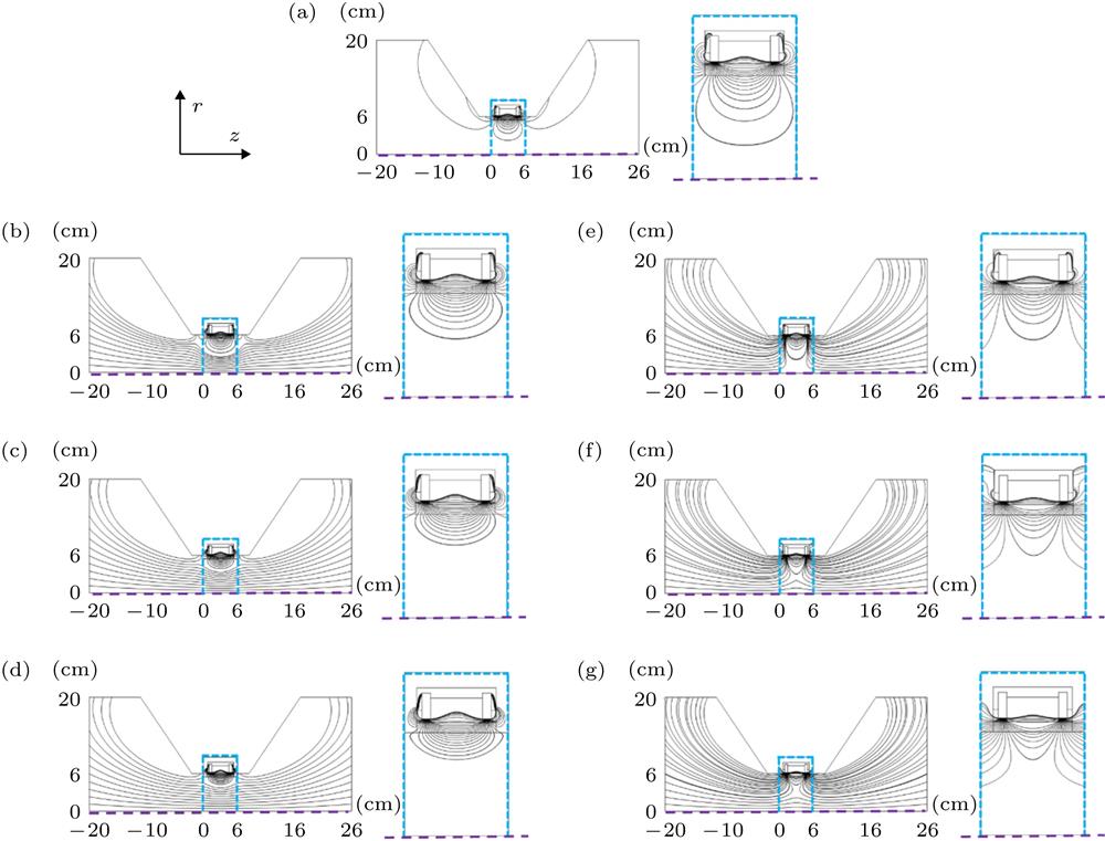
    Fig. 2. The distribution of the magnetic induction line vs. the current in electromagnetic coils: (a) 0 A; (b) 5 A; (c) 10 A; (d) 15 A; (e) –5 A; (f) –10 A and (g) –15 A. The purple dotted line is the center axis of the cylindrical cathode and the magnified area of the cylindrical cathode is marked by the blue square.磁感线分布与电磁线圈电流的关系, 右侧为筒形阴极内的磁感线分布放大图 (a) 0 A; (b) 5 A; (c) 10 A; (d) 15 A; (e) –5 A; (f) –10 A; (g) –15 A. 图中紫色虚线为筒形阴极中央轴, 蓝色方框中的部分为筒形阴极的放大区域
    The Ar+ ion distribution in the cylindrical cathode vs. the current in electromagnetic coils: (a) 0 A; (b) 5 A; (c) 10 A; (d) 15 A; (e) –5 A; (f) –10 A and (g) –15 A. The purple dotted line is the center axis of the cylindrical cathode, the gray square is the target and the blue line is the contour line of 1×10¹⁷ m–3.不同电磁线圈电流条件下筒形阴极内Ar+离子分布 (a) 0 A; (b) 5 A; (c) 10 A; (d) 15 A; (e) –5 A; (f) –10 A; (g) –15 A. 图中紫色虚线为中央旋转轴, 灰色区域为靶材, 蓝线为1×10¹⁷ m–3的密度等值线
    Fig. 3. The Ar+ ion distribution in the cylindrical cathode vs. the current in electromagnetic coils: (a) 0 A; (b) 5 A; (c) 10 A; (d) 15 A; (e) –5 A; (f) –10 A and (g) –15 A. The purple dotted line is the center axis of the cylindrical cathode, the gray square is the target and the blue line is the contour line of 1×10¹⁷ m–3. 不同电磁线圈电流条件下筒形阴极内Ar+离子分布 (a) 0 A; (b) 5 A; (c) 10 A; (d) 15 A; (e) –5 A; (f) –10 A; (g) –15 A. 图中紫色虚线为中央旋转轴, 灰色区域为靶材, 蓝线为1×10¹⁷ m–3的密度等值线
    Threshold voltage of HiPIMS discharge vs. the current in the electromagnetic coil.HiPIMS放电的起辉电压随电磁线圈电流的变化
    Fig. 4. Threshold voltage of HiPIMS discharge vs. the current in the electromagnetic coil.HiPIMS放电的起辉电压随电磁线圈电流的变化
    The plasma density distribution vs. the current in electromagnetic coils: (a) 0 A; (b) 5 A; (c) 10 A; (d) 15 A; (e) –5 A; (f) –10 A and (g) –15 A. The purple dotted line is the center axis of the cylindrical cathode.等离子体密度分布与电磁线圈电流的关系 (a) 0 A; (b) 5 A; (c) 10 A; (d) 15 A; (e) –5 A; (f) –10 A; (g) –15 A. 图中紫色虚线为中央旋转轴
    Fig. 5. The plasma density distribution vs. the current in electromagnetic coils: (a) 0 A; (b) 5 A; (c) 10 A; (d) 15 A; (e) –5 A; (f) –10 A and (g) –15 A. The purple dotted line is the center axis of the cylindrical cathode.等离子体密度分布与电磁线圈电流的关系 (a) 0 A; (b) 5 A; (c) 10 A; (d) 15 A; (e) –5 A; (f) –10 A; (g) –15 A. 图中紫色虚线为中央旋转轴
    Spatial distribution of the deposition rates: (a) Deposition rate on the central axis depends on the diffusion distance and the coil currents; (b) deposition rate at the distance of 8 cm from the cylindrical cathode at different coil currents; (c) deposition rate distribution at different distances from the cylindrical cathode when the coil current is 15 A.沉积速率的空间分布 (a) 不同线圈电流下中央轴沉积速率随扩散距离的变化; (b) 不同线圈电流下距筒形阴极8 cm处截面上的沉积速率分布; (c) 线圈电流15 A时不同距离的截面上的沉积速率分布
    Fig. 6. Spatial distribution of the deposition rates: (a) Deposition rate on the central axis depends on the diffusion distance and the coil currents; (b) deposition rate at the distance of 8 cm from the cylindrical cathode at different coil currents; (c) deposition rate distribution at different distances from the cylindrical cathode when the coil current is 15 A.沉积速率的空间分布 (a) 不同线圈电流下中央轴沉积速率随扩散距离的变化; (b) 不同线圈电流下距筒形阴极8 cm处截面上的沉积速率分布; (c) 线圈电流15 A时不同距离的截面上的沉积速率分布
    The plasma flow pictures vs. the electromagnetic coil currents: (a) The coil current is positive; (b) the coil current is negative.不同线圈电流时的等离子体束流辉光照片 (a) 线圈电流为正; (b) 线圈电流为负
    Fig. 7. The plasma flow pictures vs. the electromagnetic coil currents: (a) The coil current is positive; (b) the coil current is negative.不同线圈电流时的等离子体束流辉光照片 (a) 线圈电流为正; (b) 线圈电流为负
    The OES intensity at the center axis of cylindrical cathode vs. the electromagnetic coil currents.不同的线圈电流时筒形阴极中央轴上的光谱强度
    Fig. 8. The OES intensity at the center axis of cylindrical cathode vs. the electromagnetic coil currents.不同的线圈电流时筒形阴极中央轴上的光谱强度
    Distribution of the deposition rate when the electromagnetic coil current is (a) 15 A and (b) –15 A.(a)线圈电流为15 A时沉积速率的分布; (b)线圈电流为–15 A时沉积速率的分布
    Fig. 9. Distribution of the deposition rate when the electromagnetic coil current is (a) 15 A and (b) –15 A.(a)线圈电流为15 A时沉积速率的分布; (b)线圈电流为–15 A时沉积速率的分布
    序号反应方程式反应能量/eV反应类型
    1$e + {\rm{Ar}} \to {\rm{A}}{{\rm{r}}^ + } + 2e$15.76电离
    2$e + {\rm{Ar}} \to {\rm{A}}{{\rm{r}}^m} + e$11.56激发
    3$e + {\rm{A}}{{\rm{r}}^m} \to {\rm{Ar}} + e$–11.56退激发
    4$e + {\rm{A}}{{\rm{r}}^m} \to {\rm{A}}{{\rm{r}}^ + } + 2e$4.2电离
    5$e + {\rm{Ar}} \to {\rm{Ar}} + e$——弹性
    6${\rm{Ar}} + {\rm{A}}{{\rm{r}}^ + } \to {\rm{Ar}} + {\rm{A}}{{\rm{r}}^ + }$——弹性
    7${\rm{Ar}} + {\rm{A}}{{\rm{r}}^ + } \to {\rm{A}}{{\rm{r}}^+} + {\rm{Ar}}$——电荷交换
    Table 1.

    The main reactions of simple Ar gas discharge.

    Ar气放电的主要反应表

    电磁线圈 电流/A 靶面放电 宽度/cm 最大等离子体 密度/m–3
    154.24.63×1018
    104.01.07×1019
    53.62.93×1019
    03.44.02×1019
    -52.96.80×1019
    -102.63.13×1019
    -152.37.41×1018
    Table 2. Target discharge width and maximum plasma density.
    Sui-Han Cui, Zhong-Zhen Wu, Shu Xiao, Lei Chen, Ti-Jun Li, Liang-Liang Liu, K Y Fu Ricky, Xiu-Bo Tian, K Chu Paul, Wen-Chang Tan. Simulation study on plasma discharge and transport in cylindrical cathode controlled by expanding electromagnetic field[J]. Acta Physica Sinica, 2019, 68(19): 195204-1
    Download Citation