• Chinese Journal of Lasers
  • Vol. 47, Issue 3, 302003 (2020)
Wang Haozhi1, Guo Pengfeng1, Wu Shuang1、2、*, Tao Sha1, Chen Wei1, and Zhao Xiaojie1、2
Author Affiliations
  • 1Inno Laser Technology Corporation Ltd., Shenzhen, Guangdong 518000, China
  • 2Jiangsu Weina Laser Application Technology Research Institute, Changzhou, Jiangsu 213000, China
  • show less
    DOI: 10.3788/CJL202047.0302003 Cite this Article Set citation alerts
    Wang Haozhi, Guo Pengfeng, Wu Shuang, Tao Sha, Chen Wei, Zhao Xiaojie. Bottom-Up Drilling of Transparent Materials[J]. Chinese Journal of Lasers, 2020, 47(3): 302003 Copy Citation Text show less
    Schematic and photo of experimental setup. (a) Schematic; (b) photo
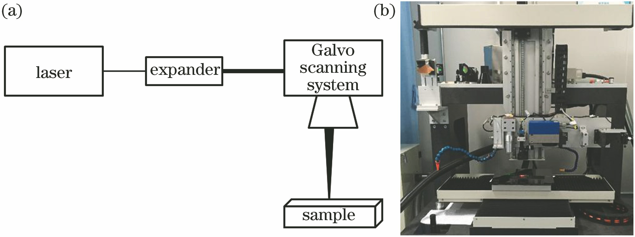
    Fig. 1. Schematic and photo of experimental setup. (a) Schematic; (b) photo
    Cut results of glass slide at different scan times with nanosecond green laser bottom-up processing. (a) 5 times; (b) 10 times; (c) 15 times; (d) 20 times; (e) 25 times; (f) 28 times, cut through
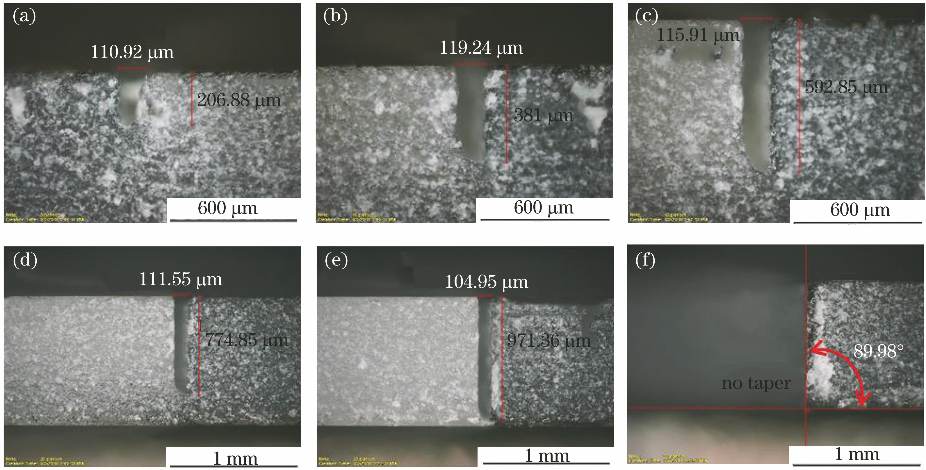
    Fig. 2. Cut results of glass slide at different scan times with nanosecond green laser bottom-up processing. (a) 5 times; (b) 10 times; (c) 15 times; (d) 20 times; (e) 25 times; (f) 28 times, cut through
    Relationship between scan times and kerf depth
    Fig. 3. Relationship between scan times and kerf depth
    Bottom-up drilling using green laser with pulse width of 12 ns. (a) Entrance; (b) exit
    Fig. 4. Bottom-up drilling using green laser with pulse width of 12 ns. (a) Entrance; (b) exit
    Bottom-up drilling using green laser with pulse width of 2 ns. (a) Entrance; (b) exit
    Fig. 5. Bottom-up drilling using green laser with pulse width of 2 ns. (a) Entrance; (b) exit
    Bottom-up drilling using picosecond infrared laser. (a) Entrance; (b) exit
    Fig. 6. Bottom-up drilling using picosecond infrared laser. (a) Entrance; (b) exit
    Bottom-up drilling using femtosecond green laser. (a) Entrance; (b) exit
    Fig. 7. Bottom-up drilling using femtosecond green laser. (a) Entrance; (b) exit
    Relation between cutting efficiency or chipping length and pulse width for two cutting methods
    Fig. 8. Relation between cutting efficiency or chipping length and pulse width for two cutting methods
    Relationship between ablation efficiency and pulse width when drilling in brittle materials using top-down method
    Fig. 9. Relationship between ablation efficiency and pulse width when drilling in brittle materials using top-down method
    Chippings generated when glass is processed by picosecond and nanosecond laser with bottom-up method. (a) Picosecond laser; (b) nanosecond laser
    Fig. 10. Chippings generated when glass is processed by picosecond and nanosecond laser with bottom-up method. (a) Picosecond laser; (b) nanosecond laser
    No.ModelWavelength /nmPulse widthMax pulse energy /μJ
    Laser 1AONano-Vanadate532<30 ns800
    Laser 2AONano-XP532<5 ns60
    Laser 3AOPico1064<15 ps60
    Laser 4AOFemto515<800 fs50
    Table 1. Parameters of lasers used in experiment
    LaserGalvano brandModelField lens brandModelField lens focal length /mm
    GreenSCANLABIntelliSCAN III 14Linos4401-461-000-21100
    InfraredSCANLABIntelliSCAN III 14Linos4401-561-000-21100
    Table 2. Parameters of galvanometer and field lens
    Wang Haozhi, Guo Pengfeng, Wu Shuang, Tao Sha, Chen Wei, Zhao Xiaojie. Bottom-Up Drilling of Transparent Materials[J]. Chinese Journal of Lasers, 2020, 47(3): 302003
    Download Citation