The conventional optical system design employs combinations of different lenses to combat aberrations, which usually leads to considerable volume and weight. In this Letter, a tailored design scheme that exploits state-of-the-art digital aberration correction algorithms in addition to traditional optics design is investigated. In particular, the proposed method is applied to the design of refractive telescopes by shifting the burden of correcting chromatic aberrations to software. By enforcing cross-channel information transfer in a post-processing step, the uncorrected chromatic aberrations are well-mitigated. Accordingly, a telescope of -8, 1400 mm focal length, and 0.14° field of view is designed with only two lens elements. The image quality of the designed telescope is evaluated by comparing it to the equivalent designs with multiple lenses in a traditional optical design manner, which validates the effectiveness of our design scheme.
Telescope objectives are frequently applied in remote sensing, photography, and security surveillance applications. The performance of refracting telescopes is typically limited by chromatic aberrations that are inherently originated from the long focal length[1]. In order to correct the induced chromatic aberrations, the most common methods are using cemented doublets or triplets that are composed of two or three optical materials with anomalous dispersion, such as and FK71[2]. However, these carefully designed telescopes are usually expensive, troublesome to manufacture due to fragility, unstable in harsh environments, and unavailable in large apertures[3]. McCarthy[4] and Wynne[5] proposed special optical layouts to eliminate longitudinal chromatic aberrations with normal glasses. Both systems consist of two or more widely spaced lens groups, which are not suitable for remote sensing and other narrow space occasions. Besides, these optical systems still suffer from lateral chromatic aberrations and other high-order monochromatic aberrations. Yang et al.[6] introduced a four-group design, where most aberrations are carefully removed. Nevertheless, the design is still too long with easily more than seven components, increasing the manufacturing and assembly costs.
With the maturing of diffractive optical elements (DOE) in design theory and manufacturing, they are more and more frequently used to decrease secondary spectra based on their particular dispersion feature. These designs can have much larger apertures compared to refractive counterparts, yet the good image quality and high transmission can only be achieved in a narrow-band spectrum[7]. Some reflecting telescopes are also subject to chromatic aberrations due to the existence of corrective lenses in the front or rear group, for example, the famous pan-Cassegrain system, where the secondary spectrum can be considerable[8].
We propose a tailored design scheme that utilizes the benefits of a digital imaging processing technique to alleviate the burdensome chromatic aberration correction from optical design. The optical–digital design chain includes firstly an optical design optimization procedure to obtain the optical layout with quasi-monochromatic imaging performance. After that, digital processing is implemented to recover the sharpness of other color channels to fulfill a broad-band design. Results show that a comparable performance can be achieved in a two-lens design with our method when compared with its classic multi-lens counterparts.
Sign up for Chinese Optics Letters TOC. Get the latest issue of Chinese Optics Letters delivered right to you!Sign up now
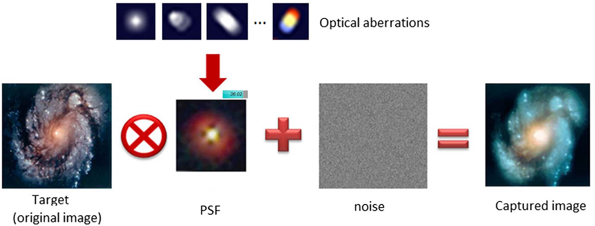
In classic Fourier optics, the imaging systems are considered as linear systems, where the point spread function (PSF) distribution is regarded as spatially invariant[9], at least within a local patch of a certain size. Under this assumption, the noise has a devastating influence when recovering the image. We consider the following well-known image formation: where represents different optical aberrations, and are the PSFs in matrix form, is the target scene in vector form, stands for various noise in the image formation, and is the obtained image on the detector.
The image formation model is shown in Fig. 1. Different optical aberrations lead to different pattern distributions in PSFs and degrade the captured images in different ways.
Figure 1.Imaging model is the comprehensive impact of the target scene, PSF, and noise.
The digital correction of optical aberrations therefore becomes solving an inverse problem, expressed as where the first term is the data fitting that describes the deviation between the target and captured image, and the second term is a set of natural image priors, for example, total variation prior , with as the gradient operator[10]. When mentioning a specified channel , is substituted by . Generally, this can be solved effectively by the alternating direction method of multipliers (ADMM)[11].
Recently, one new cross-channel prior proposed by Heide et al.[12,13] has shown that this term can be represented mathematically in the regularization term, which can be expressed as where is the reference sharp channel, and stands for the specified image channel with different blur kernels. The core of using cross-channel prior to digitally correct the chromatic aberrations lies in the fact that the edges in natural images share the same locations for different color channels. The assumptions are
The mathematical forms of the cross-channel prior in Eqs. (3) and (4) are approximations of the fact that flat regions and luma changes in sharp images show a relatively lower energy, but chroma changes (chromatic aberrations) are penalized in a sparsity regularization term. Details can be found in Refs. [12,13].
In the implementation, we use the state-of-the-art blind deconvolution algorithm to resolve the latent images that are not corrected optically[14]. Notice that unlike other work that enforces the cross-channel information sharing as an additional prior term (e.g., Refs. [12,13]), this method includes the cross-channel information transfer in the data fitting term, as represented in Eq. (4). This property leads to much stronger pixel-wise fitting that is especially beneficial in our application scenarios where one of the color channels is sharp, while others are significantly blurred. Refer to the original Letter for more details: where the convolution matrix implements the first derivatives in the and directions of the image.
In essence, we design the telescope at a specific wavelength (e.g., 550 nm) within a narrow spectrum, which results in a well-corrected image in one color channel (e.g., green). This sharp channel is a reference channel that benefits the information sharing to the other two color channels; hence, the residual chromatic aberrations can be digitally corrected by a post-processing step.
It is worth noting that the reference wavelength is not constrained at one specific wavelength, but any wavelength in the given range. This drastically extends the design space in the optical optimization stage, which also leads to easier correction for other optical aberrations.
We demonstrate this design scheme with a telescope design. The specifications of the proposed telescope are listed in Table 1. Instead of using the typical 486 nm, 587 nm (primary), and 656 nm as the representative wavelengths for the visible spectrum, our method requires only a quasi-monochromatic wavelength, and in our case 600–650 nm is selected as the desirable spectrum. Therefore, both the longitudinal and lateral chromatic aberrations are greatly reduced. Two lenses using normal glasses ZF8 and LaK3 are chosen to form the compact form factor with a more than 1000 mm back focal length, thereby providing an optimal layout for where volume and weight constraints are prominent in practice. As a result, the total length is less than 1300 mm, indicating a compact form factor.
Items
Specifications
Focal length
1400 mm
F-number
8
Field of view
1.16°
Wavelengths
486 nm, 587 nm (primary), and 656 nm
Back focal length
>1000mm
Pixel size
5.5μm
Detector resolution
4096×3072
Pixel format
Bayer RGB
Table 1. Specifications of the Exemplary Telescope
Figure 2 shows the schematic layout of the proposed optical system. All of the surfaces are spherical except the fourth surface, which is a conic surface (). From the perspective of the modulation transfer function (MTF) curves shown in Fig. 3 and the spot diagram shown in Fig. 4(a), respectively, we see that ours achieves approximately a diffraction limited performance. It is not surprising to see significant performance drop if this system works in the entire visible spectrum [Fig. 4(b)]. We leave such chromatic aberrations to be corrected in the digital processing program.
Figure 2.Schematic layout of the proposed optical system.
Figure 4.(a) Spot diagram of the quasi-monochromatic design using the proposed joint method. (b) Spot diagram of the visible spectrum using the conventional design method. The scale difference shows the considerable chromatic aberrations that are unnecessary to correct by using the proposed joint method.
For comparison, we use Wynne’s methods[5] to design the telescope for the same specifications. The final optimized result (shown in Fig. 5) uses four groups of cemented apochromatic triplets and doublets to obtain a comparable imaging performance compared with the proposed design. The image quality is evaluated in terms of spot diagram, as shown in Fig. 6. In addition, the total length is about 1600 mm, which is longer than our proposed design.
Figure 5.Classic design using Wynne’s method[5] to achieve a comparable design under the same specifications in Table 1.
Notice that the design is to eventually work in the visible spectrum, and therefore, we compare the image performance of our design and the Wynne design in simulation. We simulate the raw images and add Gaussian noise with a variance of 0.005 for both designs in Zemax with the image simulation function, as shown in Figs. 7(a) and 7(b), respectively. We apply our digital correction algorithm on the raw image as explained by Eqs. (1)–(5). The image quality is significantly improved, as shown in Fig. 7(c). The zoom-in patches illustrate details for better visualization. We calculate the peak signal-to-noise ratio (PSNR) with respect to the original input image for quantitative comparison. For the Wynne design, the PSNR is 22.7 dB, and, for ours with digital correction, PSNR is improved to 24.8 dB. This indicates that our joint design shows better image quality compared to the conventional design with Wynne’s method but with many fewer optical components in the hardware.
Figure 7.Performance comparison of the conventional and our designs. (a) Raw image simulated with the proposed design. (b) Image simulated with Wynne’s design. (c) Final corrected image with the proposed method. All of the results are simulated in Zemax with the image simulation function. Our joint design results outperform the conventional Wynne design.
We have run the same tests for different source images, and our method has consistent performance in terms of PSNR. On the other hand, we believe it is more reasonable to test the results with quantitative image quality metrics, e.g., MTF. We use the 12233 chart of International Organization for Standardization (ISO) as a standard input for image quality evaluation. Accordingly, the slanted-edge analysis method is used[15]. The blurred image from the quasi-monochromatic design is shown in Fig. 8(a), and the resolved image is revealed in Fig. 8(b). A selected window patch on the same position of both images is used to implement the MTF evaluation. As shown in Fig. 9, the results demonstrate the viability of the deconvolution algorithm based on chromatic priors, and the residual chromatic aberrations are mostly removed. Therefore, the blue and green channels that are neglected on purpose during the optical design now exhibit good imaging quality as the primary red channel. Due to a possible metamerism issue that is caused by the spectrum deviation of the design channel and the red–green–blue (RGB) Bayer filter of the sensor, the resolved image quality is exhibited as slightly lower than that of synthetic MTF evaluation.
Figure 8.Standard ISO 12233 charts of (a) the simulated image and (b) the deconvolved image.
In conclusion, the proposed joint design scheme is validated by applying it to a practical telescope design. The synthetic implementation results exhibit great impact in reducing the complexity of the opto-mechanical structure. We note that this method is not limited to refracting telescope designs, but is also applicable to diffractive and/or catadioptric telescope designs.
References
[1] H. Gross, H. Zügge, M. Peschka, F. Blechinger. Handbook of Optical Systems, Volume 3: Aberration Theory and Correction of Optical Systems(2007).
[2] R. Kingslake, R. B. Johnson. Lens Design Fundamentals(2010).