
Xinyao LIU, Qingyang WEI, Tianpeng XU, Zhaohui ZHANG. Highly sensitive coded aperture gamma imaging system based on a SPECT probe[J]. NUCLEAR TECHNIQUES, 2022, 45(12): 120401
- NUCLEAR TECHNIQUES
- Vol. 45, Issue 12, 120401 (2022)
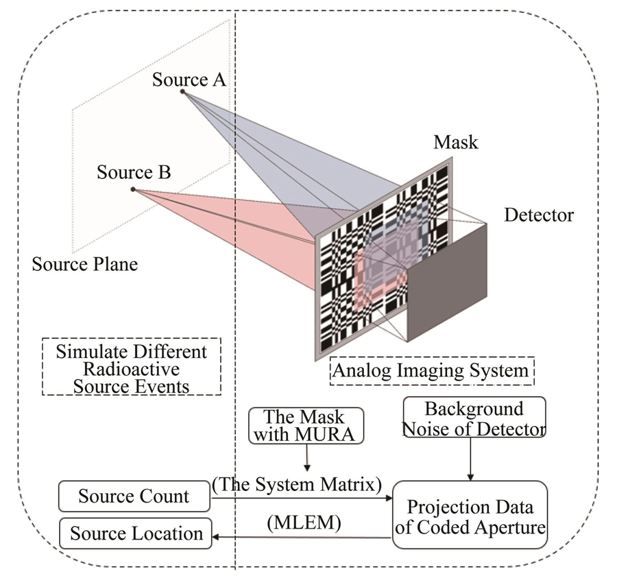
Fig. 1. Flow chart of physical detection process simulation of coded aperture γ imaging system
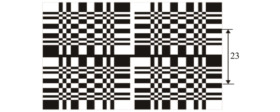
Fig. 2. Pattern of the coded mask: MURA(45×45)
Fig. 3. Illustration of the geometry setup of the imaging system
Fig. 4. Two-dimensional model of photon counting estimation for detection
Fig. 5. Reconstructed images of a point source at different distances and different FOV angles: the 1st, 2nd, 3rd, 4th, 5th and 6th columns are positions at (-29.64°, 23.65°), (0°, 23.65°), (0°, 0°), (28.66°, 0°), (29.64°, 0°) and (-14.87°, -14.87°); the 1st, 2nd and 3rd rows are the distance between the radiation source and the detector of 10 m, 15 m and 18 m, respectively
Fig. 6. Reconstruction images of 1.11×10⁶ Bq 137Cs at distance of 4 m from detector with different FOV angles: the 1st, 2nd, 3rd, 4th and 5th columns are positions at (-29.64°, 23.65°), (0°, 23.65°), (0°, 0°), (28.66°, 0°) and (-14.87°, -14.87°), respectively
Fig. 7. (a) Reconstructed image of 3.7×10⁷ Bq 137Cs point source at distance of 10 m from detector with FOV angle (0°, 0°), Gaussian fitting of normalized data points of pixel intensity distribution along the
X direction (b) and the
Y direction (c) of a single point source
Fig. 8. Reconstructed images of two 3.7×10⁷ Bq 137Cs sources at the distance of 10 m from detector with acquisition time of 1 s
|
Table 1. Parameters of imaging system
| ||||||||||||||||||||||||||||||||||
Table 2. CNR of reconstructed images from different positions of radioactive sources

Set citation alerts for the article
Please enter your email address
© Copyright 2018-2021 | Chinese Laser Press. All Rights Reserved 沪ICP备15018463号-20