Abstract
Based on dense wavelength-division multiplexing technology, frequency transfer and time synchronization are simultaneously realized over a compensated cascaded fiber link of 430 km, which is a part of the Beijing–Shanghai optical fiber backbone network. The entire cascaded system consists of two stages with fiber links of 280 and 150 km, respectively. To keep high symmetry and low noise, specific bi-directional erbium-doped fiber amplifiers are used to compensate the large optical attenuation of each fiber link. When the compensation servo is active in every stage, the cascaded system achieves the stability of at 1 s and at , for frequency transfer. It is also verified that the actual results of the cascaded system are in good agreement with the theoretical ones calculated from error theory. Simultaneously, after calibration of each stage, time synchronization is also realized. The final accuracy of the whole system is within 94 ps.High-precision frequency transfer is of great importance in many application areas, such as clock comparison, basic physical constants measurement (fine structure constant[1], neutrino speed), and so on. Owing to the influence of atmospheric environment, the traditional satellite-based method will not meet the demands of the increasing accuracy of an atomic clock[2]. In recent years, time and frequency transmission based on optical fiber has been developed rapidly. The results show that the method can provide higher frequency stability[3–7].
In order to achieve high-precision frequency transmission in a quasi-national territory or even on a continental scale, it is necessary to verify field link transfer of ultralong distances. However, when frequency transfer over long distances is considered, there are two questions that should be taken into account. The first is backscattering[8], which may not be serious in short distance transfer[9], but with ultralong distances the accumulated backscattering noise would seriously affect the transfer performance. In the laboratory’s 480 km microwave transmission[10], it adopts eight single-path bidirectional amplifiers without considering the free propagation of backscattering noise. Therefore, the achieved stability observed is not very good, especially in a short time period. The second is the ultimate limitation on feedback bandwidth. Based on the round-trip compensation method[3], the link loss and the cumulative noise increase with the distance of the fiber link, while the compensation bandwidth and noise suppression ratio decrease with the increase of the link length[11]. Although transfer over 1840 km[5] fiber has been demonstrated with a good result owing to the narrow linewidth of the transmitted optical signal and intrinsic low noise of the link, the limit is critical for the transfer of a microwave signal that is usually modulated on an optical carrier with a relatively large linewidth. To answer both questions, the cascaded method is a good choice for microwave transfer, and some experiments on cascaded systems have been carried out with good performance[12,13]. In this Letter, in addition to exploiting a cascaded system, specialized bidirectional erbium-doped fiber amplifiers (Bi-EDFAs) with low noise and high symmetry[14] are also used in the cascaded link. With these two methods, the high-precision frequency transfer is demonstrated over a compensated fiber link of 430 km, which is a part of the Beijing–Shanghai optical fiber backbone network. In some cases, such as long-baseline interferometry[15], deep space exploration, and x ray particle acceleration, not only the frequency reference is needed but the high-precision clock synchronization is also a basic requirement. So, apart from the transfer of microwave frequency, time transfer and synchronization are also achieved based on dense-wavelength division multiplexing (DWDM) technology.
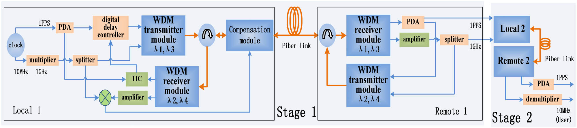
The schematic diagram of the cascaded system for high-precision optical fiber frequency transfer and time synchronization is shown in Fig. 1, which contains two stages. For simple illustration, only stage 1 is described in detail. The same process can be applied to stage 2. At the local end, the 10 MHz frequency signal is multiplied to a higher frequency (1 GHz) because generally at higher frequency levels the distributed feedback (DFB) laser has a lower-intensity noise and can improve the signal-to-noise ratio of the compensation system. Then, the signal is modulated on an optical signal () through a transmitter module that contains two DFB lasers with a linewidth of 1 MHz, two electro-optic modulators, a DWDM, and a polarization scrambler. The polarization scrambler is used to decrease the polarization mode dispersion (PMD). After a circulator, the signal enters the fiber link. At the remote end, the frequency signal is demodulated by the receiver module, and one part of the obtained signal is delivered to the user end or the next stage. Owing to the phase noise accumulated along the fiber link, the stability of the transmitted signals is prone to degrade without effective phase-noise compensation. The roundtrip method is commonly used for noise cancellation in fiber-based time and frequency transfer. A part of the recovered signal at the remote end is modulated on another optical carrier (the wavelength is to avoid the influence of backscattering, ) and sent back to the local end. The returned frequency is sent to the phase discriminator with the reference frequency to obtain the error signal of 1 GHz frequency. Then, the error signal is processed and compensated by the optical compensation module[16], which is located after the circulator at the local end, resulting in an accurate replication of the frequency signal at the remote end. The performance of the transmission system is obtained by phase discrimination between the 1 GHz reference signal and the final frequency output.
Sign up for Chinese Optics Letters TOC. Get the latest issue of Chinese Optics Letters delivered right to you!Sign up now

Figure 1.Configuration of the cascaded system for frequency transfer and time synchronization. PDA: Pulse distribution amplifier.
As for the time signal, it is also locked to the atomic clock. Based on the wavelength division multiplexing technology (, ), it goes through the same fiber link as the frequency signal does. The variation caused in the fiber link by temperature and humidity is almost the same, and the phase noise of time signal is also cancelled by the compensation module. Here, a digital delay controller, which can control the delay of a signal that goes through it, and a time interval counter (TIC) are used to realize time synchronization. The TIC is to obtain the roundtrip time delay. It takes two steps. In the laboratory, a short fiber is adopted to replace the fiber link. The delay of the digital delay controller is set as delay1 to make the time signal received at the remote end strictly 1 second later than the local reference. The value of the TIC is T1. In the field experiment, where the local end and remote end are not placed together, the delay of the digital delay controller is assumed to be delay2 to achieve time synchronization. The value of the TIC changes to T2. As reported in our previous literature[16,17], delay2 is calculated by where . It is the asymmetrical delays caused by Bi-EDFAs, dispersion effect[18] ( is the dispersion coefficient and is the fiber length), PMD, and the Sagnac effect in the fiber link, which are measured in advance and revised in the final controlled delay. The input power of detectors should be maintained the same in the two steps. The synchronization performance is obtained by analyzing the delay variation between the reference and that received at the remote end.
Stage 2 follows the same process as stage 1 to reach frequency replication and time synchronization. At the output, the 1 GHz frequency is downconverted to 10 MHz for the user end. As for the properties of the entire cascaded system, they are obtained by comparing the reference signals of stage 1 with the output signals of stage 2 after the two stages both achieve a stable status. All the frequency and time performances are recorded by phase discriminators and TICs, respectively. The bandwidth of the phase discriminators is 5 Hz, and the TICs used are Stanford SR620 with a sample interval of 1 s.
As introduced above, it is necessary to verify the performance of ultralong distance transfer of frequency and time synchronization in a field fiber network. Therefore, we adopt a part of the Beijing–Shanghai optical fiber backbone network to test the cascaded system. The practical application and field links are shown in Fig. 2. The field link of stage 1 is from the city of Changzhou to Wuxi and Suzhou, and then back to Changzhou, with a total length of 280 km. The link of stage 2 is just from Changzhou to Wuxi, and then back to Changzhou, with a length of 150 km. In the two stages, the Changzhou node acts as both the local and remote end. In stage 1, three highly symmetrical and low-noise Bi-EDFAs are inserted in the Wuxi and Suzhou nodes to compensate for the high loss of the 280 km fiber link. The construction of such Bi-EDFAs can effectively reduce the backscattering noise along the fiber[14]. While in stage 2, one Bi-EDFA is used in Wuxi.
Figure 2.Field cascaded transfer system.
When the two stages are stabilized by the optical compensation method, the performance of the cascaded system can be acquired. Frequency stability is usually expressed by the overlapping Allan deviation, which is a statistical calculation of the phase difference collected by the phase discriminators. The frequency stability of the cascaded 430 km is illustrated in Fig. 3. The short-term stability of the 1 GHz signal is at 1 s, and the long term is at . It is observed that, compared with the open-loop case ( at 1 s and at ), the phase noise in the closed loop is effectively suppressed. In contrast to the results (worse than at 1 s) obtained by using a series of multiple bidirectional optical amplifiers at the same distance scale[10], the stability using the cascaded process is improved by almost one order of magnitude, especially in the short term. This reinforces the importance of the cascaded system for ultralong distance transfer of the microwave signal. The optical noise floor is obtained by measuring the phase difference between the reference signal at the local end and the received signal at the user end using several short fibers to replace the 280 and 150 km fiber links without any change of other devices. For conformity, the loss of these short fibers is adjustable so that it can make sure that all the input powers of Bi-EDFAs and detectors are kept the same as in the field experiment.
Figure 3.Frequency stability comparison of the 430 km cascaded system between the closed and open loop.
The phase noises of each stage in a cascaded system are independent of each other and have randomness. According to the error theory[19], if a system has multiple random errors and the errors are independent of each other, the total error is the root mean square (RMS) of errors at each level. Theoretically, the stability of the cascaded system should be the RMS errors of two-stage transmission systems. The experimental results of stage 1, stage 2, and the cascaded system demonstrated in Figs. 4(a) and 4(b) give the theoretically calculated results by the stability of the two-stage system. It can be observed that the experimental value is in good agreement with the theoretical one.
Figure 4.Frequency stabilities of the closed loop: (a) stage 1, stage 2, and cascaded system; (b) theoretical and experimental results.
After the optical compensation servo works, the time signal also reaches a stable state like the frequency. The comparison of the time delay fluctuations between the closed loop and open loop of the 430 km cascaded system are shown in Fig. 5. The RMS value of the time delay fluctuation in a closed loop is only 57 ps and the mean value is 94 ps. Relative to the long time drifts in the open loop, it is still verified that the compensation effect is obvious.
Figure 5.Time delay fluctuations in the closed loop and open loop of the 430 km cascaded system.
The time delay fluctuation results of stage 1, stage 2, and the cascaded system in a closed loop can be observed in Fig. 6. To tell one time series from another, the results of stage 2 and the cascaded system have been shifted vertically by 400 and 800 ps, respectively. The time synchronization accuracy of stage 1 and stage 2 are 47 and 34 ps, respectively. The result of the cascaded link is marginally higher than the sum of that of stage 1 and stage 2, which may be because of some measurement inaccuracy among the different TICs.
Figure 6.Time delay fluctuation results of stage 1, stage 2, and the cascaded system in the closed loop.
Conventionally, time synchronization at such distance scales is realized by GPS or Beidou time service and time keeping through atomic clocks. However, both methods have a limit on the synchronization accuracy and the cost of operating and maintaining such devices is unsustainable. Through the above results, it can be found that an optical fiber cascaded system cannot only reduce the manufacturing cost of atomic clocks but also improve the time synchronization accuracy.
In this Letter, based on the DWDM technology and the cascade process, high-precision microwave frequency transfer and time synchronization over a 430 km field fiber link are achieved. The field link is a part of the Beijing–Shanghai optical fiber backbone network, and the cascaded system contains two stages. One of the fiber links is Changzhou–Wuxi–Suzhou–Wuxi–Changzhou, with 280 km length, and the other is Changzhou–Wuxi–Changzhou, with 150 km length. To compensate optical losses of both links, specific Bi-EDFAs are inserted in Wuxi and Suzhou. When every stage reaches a stable status by the optical compensation method, the frequency stability of the cascaded 430 km system is at 1 s and at . Comparing the experimental results with the theoretical ones calculated by error theory, it is observed that they are in good agreement. After the time calibration of two stages, the time synchronization accuracy of the cascaded system is 94 ps. With such a performance, it can be foreseen that by exploiting more stages, microwave transfer over thousands of kilometers would be possible. In fact, this also provides a certain basis for the future construction of high-precision optical fiber-based time and microwave frequency transmission network in a quasi-national or continental territory.
References
[1] S. M. Foreman, K. W. Holman, D. D. Hudson, D. J. Jones, J. Ye. Rev. Sci. Instrum., 78, 021101(2007).
[2] W. H. Tseng, S. Y. Lin, K. M. Feng, M. Fujieda, H. Maeno. IEEE Trans. Ultrason. Ferroelectr. Freq. Control, 57, 161(2010).
[3] O. Lopez, A. Amy-Klein, C. Daussy, C. Chardonnet, F. Narbonneau, M. Lours, G. Santarelli. Eur. Phys. J. D, 48, 35(2008).
[4] O. Lopez, A. Haboucha, B. Chanteau, C. Chardonnet, A. Amy-Klein, G. Santarelli. Opt. Express, 20, 23518(2012).
[5] S. Droste, F. Ozimek, T. Udem, K. Predehl, T. W. Hänsch, H. Schnatz, G. Grosche, R. Holzwarth. Phys. Rev. Lett., 111, 110801(2013).
[6] N. Cheng, W. Chen, Q. Liu, D. Xu, F. Yang, Y. Z. Gui, H. W. Cai. Chin. J. Lasers, 42, 0705003(2015).
[7] Y. Bai, B. Wang, C. Gao, J. Miao, X. Zhu, L. Wang. Chin. Opt. Lett., 13, 061201(2015).
[8] H. Feng, S. Xiao, L. Yi, Z. Zhou, J. Shi, T. Qi. Chin. Opt. Lett., 11, 020607(2013).
[9] O. Lopez, A. Amy-Klein, M. Lours, C. Chardonnet, G. Santarelli. Appl. Phys. B, 98, 723(2010).
[10] Ł. Śliwczyński, P. Krehlik, A. Czubla, Ł. Buczek, M. Lipinski. Metrologia, 50, 133(2013).
[11] O. Lopez, A. Haboucha, F. Kefelian, H. F. Jiang, B. Chanteau, V. Roncin, C. Chardonnet, A. Amy-Klein, G. Santarelli. Opt. Express, 18, 16849(2012).
[12] M. Fujieda, M. Kumagai, S. Nagano. IEEE Trans. Ultrason. Ferroelectr. Freq. Control, 57, 168(2010).
[13] C. Gao, B. Wang, X. Zhu, Y. B. Yuan, L. J. Wang. Rev. Sci. Instrum., 86, 093111(2015).
[14] Q. Liu, W. Chen, D. Xu, N. Cheng, F. Yang, Y. Gui, H. Cai, S. Han. Chin. Opt. Lett., 13, 110601(2015).
[15] D. S. Robertson. Rev. Mod. Phys., 63, 899(1991).
[16] W. Chen, Q. Liu, N. Cheng, D. Xu, F. Yang, Y. Z. Gui, H. W. Cai. Photon. J., 7, 7901609(2015).
[17] N. Cheng, W. Chen, Q. Liu, D. Xu, F. Yang, Y. Z. Gui, H. W. Cai. Chin. J. Lasers, 42, 0705003(2015).
[18] L. Han, L. Liu, Z. Yu, H. Zhao, X. Song, J. Mu, X. Wu, J. Long, X. Liu. Chin. Opt. Lett., 12, 010603(2014).
[19] Y. T. Fei. Error Theory and Data Processing(2004).