Lei Chen, Keng C. Chou, "Revisiting the absorption and transmission properties of coupled open waveguides," Photonics Res. 6, 1003 (2018)
Copy Citation Text
Open waveguides are widely used in modern photonic devices, such as microstructured fiber filters and sensors. Their absorption and transmission spectra are the most important properties in determining the overall performance of the photonic devices. The imaginary parts of their eigenvalues have been commonly used to calculate the absorption and consequently the transmission spectra. Here we show that this formulism is generally incorrect and not consistent with the simulation results obtained by the beam propagation method. We revisit the fundamental theory for the absorption of open waveguides and present a general formulism. We found that parity-time-symmetry transitions, which have been conventionally ignored, play a critical role in the properties of the coupled waveguide. The absorption and transmission are highly dependent on the physical length of the system. On the basis of our findings, optimization criteria for designing photonic sensors and filters are presented.
1. INTRODUCTION
Many photonic crystal fiber (PCF) devices, such as PCF filters [1,2] and sensors [3–5], utilize the coupling between the dominant core and cladding eigenmodes to produce the desired transmission resonance. In these devices, the refractive indices (RIs) of the eigenmodes and the dispersion can be precisely controlled by manipulating their geometrical structures. As a result, the resonance wavelength is tunable and has a narrow bandwidth, which is desirable for designing an optical device.
Conventionally, the absorption spectrum of a PCF is calculated by Beer’s Law using the imaginary part of its eigenmode’s RI as the absorption coefficient [6–9]. In this formulism, the dominant core eigenmode and dominant cladding eigenmodes are decoupled because of symmetry protection [10]. The symmetry protection originates from the orthogonality of the eigenmodes of a Hermitian Hamiltonian. However, the assumption that these two eigenmodes are decoupled is not generally correct for a non-Hermitian Hamiltonian [11]. When these two eigenmodes are coupled, energy transfer between these two modes occurs. In this case, the absorption can no longer be described by the simple exponential decay (Beer’s Law) because of the interference between these two eigenmodes. As described below, our study shows that Beer’s Law is not consistent with the simulation results obtained by the beam propagation method (BPM).
In the current study, we develop a formulism to calculate the absorption and transmission spectra for a non-Hermitian Hamiltonian of an open optical system. The parity-time (PT) symmetry of the system plays a critical role in the aforementioned interference between the eigenmodes. Interestingly, we found that the PT phase transition depends on both the waveguide absorption and the input wavelength. Consequently, the absorption and transmission may exhibit dramatic changes, instead of a mono-exponential decay or gain when light propagates along the waveguide. The current study shows that adjusting the length of a waveguide is also critical for optimizing its absorption and transmission properties. On the basis of our formulism, several optimization criteria for designing photonic crystal sensors and filters are presented. In addition, we show that an increase in the imaginary part of the eigenmode is a sufficient condition, not a necessary condition, for an increased absorption.
Sign up for Photonics Research TOC. Get the latest issue of Photonics Research delivered right to you!Sign up now
2. NON-HERMITIAN COUPLED WAVEGUIDES
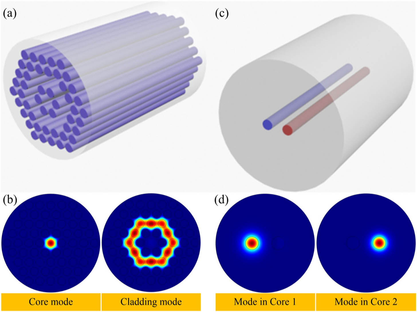
For simplicity, a PCF [Fig. 1(a)] with coupled core and cladding modes [Fig. 1(b)] can be mathematically represented by a two-core fiber [Fig. 1(c)] with two coupled modes, as shown in Fig. 1(d). The Hamiltonian of the system or any coupled waveguides can be written as () where is the angular frequency, are the complex mode RIs, and are the annihilation operators for the core and cladding modes, respectively, and are the creation operators for the core and cladding modes, respectively, and describes the effective evanescent coupling. The Heisenberg equation of motion for these two annihilation operators can be written as with and .
Figure 1.(a) Representative PCF structure and (b) its dominant core and cladding eigenmodes. (c) Equivalent two-core fiber and (d) its eigenmodes.
Conventionally, the off-diagonal elements ( and ) are treated as either real numbers [9] or conjugated complex numbers [6]. Both cases lead to a spontaneous PT-symmetry breaking [8]. In general, the coupling coefficients are defined by and , where denotes the electric fields in the th core. At a given wavelength, the spontaneous PT-symmetry-breaking phase transition takes place when the medium loss is negligible ( are real numbers). In this case, is also a real number. When are complex numbers, is also a complex number; therefore, an explicit PT-symmetry-breaking phase transition takes place. For simplicity, we consider in Eq. (3), with being a complex number. As described later, this is consistent with the simulation results obtained by the finite element method (FEM).
To compare the transmission spectrum with the imaginary part of the eigenvalues for the eigenmodes (supermodes), we decompose the non-Hermitian matrix by using the biorthogonal eigenstates [12]: where and , with , , , , and . The annihilation operator can be calculated by integrating Eq. (2) over time : where with . The transmitted light intensity is given by Here, and represent the intensity of the core and cladding modes, respectively. The following discussion focuses on the absorption and transmission properties of the core mode with and , which is relevant to practical applications.
Figure 2 (solid lines) shows the calculated real and imaginary parts of the eigenmode RI ( and ) at 1.55 μm. In this calculation, we assumed that the real part of the RI for core 1 is 1.45, and core 2 has a dispersion , with at 1.55 μm. It shows a second-order phase transition and a period-halving bifurcation near . We used a two-core single-mode waveguide in the calculation; therefore, the RIs of the core and cladding modes were approximated using the RIs of the media. Practically, the mode RIs can be modified by changing the structure of the photonic crystal [13,14]. The medium loss in core 1 was set at , and we changed the medium loss in core 2 to produce the phase transition. With the first-order Markov approximation [15], it was assumed that the coupling coefficient . was used in the calculation to explain the phase transition at the phase matching point ( at 1.55 μm) originated from the explicit PT-symmetry breaking.
Figure 2.(a) Real and (b) imaginary parts of and as functions of obtained from the theory (solid lines) and the FEM simulation (dashed lines).
Simulations using the FEM were carried out to verify that the non-Hermitian Hamiltonian of the coupled optical system possesses an explicit PT-symmetry breaking (dashed lines in Fig. 2), instead of a spontaneous PT-symmetry breaking. All parameters used in the FEM were identical to those used in the quantum mechanical calculation described above. We embedded the fiber cores into silicon () with a core pitch of 12 μm. Figure 2 shows that the simulated imaginary parts of the eigenmode RI have a second-order phase transition, which confirms that it has an explicit PT-symmetry breaking, instead of a spontaneous PT-symmetry breaking.
Conventionally, the imaginary part of the eigenvalue is used to calculate the system’s absorption coefficient using [1,5]Figure 3 shows the calculated imaginary part of the eigenvalue using Eq. (7) with , , and , respectively. is not single-valued as this is a characteristic of PT-symmetry breaking [6]. The minimum value of is used to calculate the absorption [1–4,9] because light always propagates via a mode with a lower loss rather than a higher one. describes the exceptional point of the coupling phase transition [16,17]. When increases from 0.25 [Fig. 3(a)] to 1 [Fig. 3(b)], the absorption of the waveguide increases from to at 1.55 μm; consequently, the transmission decreases. When , the dispersion curves become discontinuous at 1.55 μm, which indicates a first-order phase transition. The discontinuity occurs because μ is an algebraic branch point for [18]. As a result, produces a smaller peak absorption value of [Fig. 3(c)] compared to [Fig. 3(b)]. Similar processes are obtained when the value of increases from to (solid curves in Fig. 3). In this formulism, the transmitted light experiences a constant adsorption coefficient and the intensity exhibits an exponential decay, which is consistent with Beer’s Law [1,5,9]. The transmission spectrum maintains the same lineshape when the light propagates along the waveguide.
Figure 3.Eigenvalues of the coupled system (blue) and (red) as functions of the wavelength () with of (a) 0.25 (dashed) and (solid), (b) 1 (dashed) and (solid), and (c) 1.5 (dashed) and (solid), respectively.
Figure 4 compares the transmission spectra obtained by the conventional formulism [Eq. (7)], the proposed quantum formulism [Eq. (6)], and the BPM simulations. The conventional formulism [Fig. 4(a)] fails to predict the oscillating intensity shown in the BPM simulation [Fig. 4(c)]. In contrast, the proposed quantum formulism successfully reproduced the oscillation. Figure 4(b) is slightly different from Fig. 4(c) because of the first-order Markov approximation used for . When , the imaginary parts of these two eigenmodes are equal to each other. According to Eq. (7), there are no absorption peaks in the transmission, as shown in Fig. 4(d). However, absorption peaks can be observed in both the BPM results [Fig. 4(f)] and the quantum formulism [Fig. 4(e)]. Our studies indicate that a peak in the imaginary parts of the eigenmodes is a sufficient but not necessary condition to produce an absorption peak in the transmission spectrum.
Figure 4.Transmission spectra obtained by (a), (d) the conventional formulism, (b), (e) the quantum formulism, and (c), (f) the BPM simulation with of (a)–(c) 0.25 and (d)–(f) 0. Color map scales are independent.
The quantum formulism shows various absorption lineshapes, instead of a fixed lineshape given by conventional formulism. Figure 5 shows that the transmission spectra obtained from Eq. (6) change with the value of , i.e., . Figures 5(a) and 5(d) show that the transmission lineshape is highly sensitive to the propagation length. The transmission spectrum exhibits frequency comb characteristics at a given waveguide length, which cannot be obtained by the conventional formulism. In addition, Eq. (7) produces the largest value of when [Fig. 3(b)]. However, Fig. 5(e) shows that does not exhibit the largest absorption (or highest transmission) at the resonance. For example, with in Fig. 5(d), the transmission intensity at the resonance is weaker than that in Fig. 5(e). These phenomena are unexpected from the conventional formulism.
Figure 5.Transmission spectrum as a function of the propagation length with of (a) −0.25 and (d) 0.25, (b) and (e) 1, and (c) and (f) 1.5, respectively.
The fundamental issue in the conventional formulism is that it assumes the eigenmodes ( and ) are orthogonal. In this case, these two eigenmodes are decoupled because of symmetry protection [10]. In general, if the amplitude distribution of eigenmode preserves a symmetry and does not, then and are decoupled. In this case, the absorption spectra obtained by Eqs. (6) and (7) are identical. However, the eigenmodes of and are not symmetry protected in a non-Hermitian Hamiltonian [Eq. (1)] because their eigenmodes are not orthogonal. Their eigenmodes are not orthogonal if the value of the mode overlap factor () [19] is larger than 0, as shown in Fig. 6. Their eigenmodes are orthogonal if and only if , i.e., these two cores maintain the same complex refractive index. Therefore, these two eigenmodes are coupled to each other if . As a result, in the PT-symmetry-breaking phase, one of the two eigenmodes decays within one beating cycle, and the interference vanishes. On the other hand, these two eigenmodes couple to each other in the PT-symmetry phase during light propagation and produce the interference.
Figure 6.Eigenmode overlap factor at the phase matching point (1.55 μm).
To further understand the origin of the various transmission spectra shown in Fig. 5, the phase diagram obtained from and is shown in Fig. 7. Depending on the values of , , and , the system may be in a PT-symmetry (blue) or PT-symmetry-breaking (orange) phase. When the system remains in the PT-symmetry phase [Figs. 5(a) and 5(d)], the transmission spectrum varies dramatically along the propagation direction because of the aforementioned interference between the dominant core and cladding eigenmodes. When the system is dominated by the PT-symmetry-breaking phase [Figs. 5(c) and 5(f)], the oscillation in the transmission spectrum vanishes. The transmission spectrum may undergo a different phase depending on the wavelength. Therefore, both the PT-symmetry and PT-symmetry-breaking phases can be observed in the transmission spectrum.
Figure 7.Phase diagram in a versus plot. The blue region indicates a PT-symmetry phase, and the orange region indicates a PT-symmetry-breaking phase.
An interesting phenomenon occurs when [Fig. 5(b)], which indicates a gain in the system. This system is PT symmetric in the range of 1.5425 to 1.5525 μm, but breaks the PT-symmetry outside of this wavelength region. As a result, the transmission spectra in the PT-symmetric region show dramatic oscillation until the large amplification overwhelms the oscillation. When [Fig. 5(f)], the system is mostly in a PT-symmetry-breaking phase over the useful spectral region. Because the PT-symmetry-breaking phase leads to a nearly orthogonal basis from the matrix in Eq. (4), in this case, the current quantum formulism produces an exponential decay, similar to that derived from the conventional formulism.
When designing a passive photonic crystal filter [4,5], the case shown in Fig. 5(d) allows a highly adjustable transmission. The case shown in Fig. 5(e) provides a narrow bandwidth and a length-insensitive transmission. For photonic crystal sensors [6,7,13,14], a large imaginary part near the resonant wavelength [Fig. 3(b)] should not be the only criterion since the length of the fiber also plays a critical role in the transmission [Fig. 5(d)]. The optimal design parameter should have a value of larger than 1 [Fig. 5(e)] to avoid the transmission oscillation in the PT-symmetry phase.
3. CONCLUSION
We found that the results obtained using the imaginary part of the eigenmodes to calculate the absorption spectrum of a coupled waveguide is not consistent with the results from the BPM simulation. With the quantum formulism presented in this study, we show that an increase in the imaginary part of the eigenmode is a sufficient condition, instead of a necessary condition, for an increased absorption. The PT symmetry of an optical system plays a critical role in determining the absorption properties of the coupled system. This work shows that adjusting the length of the waveguide is an effective approach to optimize the absorption and transmission. Additionally, we observed several phenomena previously unrecognized by the conventional formulism.