
Cuiying Pei, Lin Wang. Recent progress on high-pressure and high-temperature studies of fullerenes and related materials[J]. Matter and Radiation at Extremes, 2019, 4(2): 28201
- Matter and Radiation at Extremes
- Vol. 4, Issue 2, 28201 (2019)
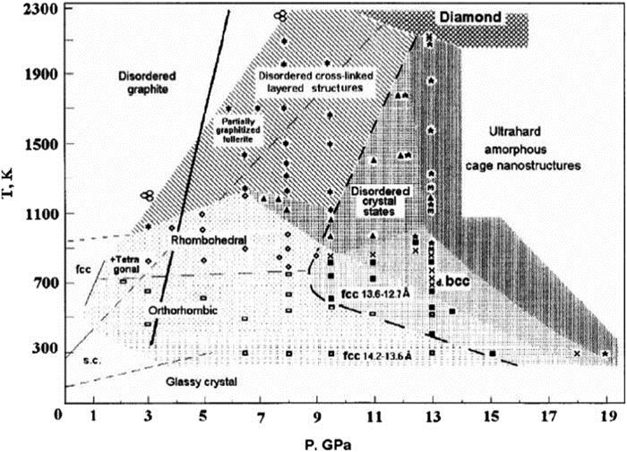
Fig. 1. Map of the P–T plane showing the various phases of C60 created under different conditions. Symbols denote some of the P–T coordinates where experiments have been carried out and samples have been treated for at least 1 min. (—) denotes the diamond/graphite equilibrium line, while (– – –) divides the semimetal and semiconductor states at T > 1100 K and the “soft” and “hard” states at T < 1100 K. Reprinted with permission from V. D. Blank et al. , Carbon 36 , 319–343 (1998). Copyright 1998 Elsevier.
![Formation of C60 polymers by [2 + 2] cycloaddition of pristine C60. (The figure has been redrawn based on Ref. 26.) Reprinted with permission from F. Giacalone and N. Martín, Chem. Rev. 106, 5136–5190 (2006). Copyright 2006 American Chemical Society.](/richHtml/MRE/2019/4/2/028201/img_2.jpg)
Fig. 2. Formation of C60 polymers by [2 + 2] cycloaddition of pristine C60. (The figure has been redrawn based on Ref. 26 .) Reprinted with permission from F. Giacalone and N. Martín, Chem. Rev. 106 , 5136–5190 (2006). Copyright 2006 American Chemical Society.
Fig. 3. Raman spectra of pristine C60 (a), polymerized dimers (b), and orthorhombic phase (c), excited by a 1064 nm line, and of the orthorhombic (d), tetragonal (e), and rhombohedral (f) phases, excited by a 568.2 nm line. Reprinted with permission from V. A. Davydov et al. , Phys. Rev. B 61 , 11936 (2000). Copyright 2000 American Physical Society.
Fig. 4. A random distribution of C60 dimers (and isolated monomers) in the (001) plane of a model crystal, which accounts reasonably well for the experimentally observed diffuse scattering intensity distribution. Only in-plane and out-of-plane C60’s that form dimers with an in-plane C60 are shown. Reprinted with permission from R. Moret et al. , Eur. Phys. J. B 37 , 25–37 (2004). Copyright 2004 Springer Nature.
Fig. 5. Schematic views of the polymer chains running along 〈110〉 cubic directions of the parent monomer lattice, for the different polymer structures. The chains are normal to the figure. The orientation of the four-membered rings is represented by the shaded bars that form an angle μ with the 〈001〉 cubic directions. The broken lines represent the 2D tetragonal and rhombohedral polymer layers that can be obtained, at least schematically, by connecting the C60 molecules of the chains by supplementary four-membered rings. Reprinted with permission from R. Moret et al. , AIP Conf. Proc. 544 , 81–84 (2000). Copyright 2000 AIP Publishing LLC.
Fig. 6. Crystal structure of the 3D C60 polymer (b) in comparison with the starting 2D polymer (a). Carbon atoms marked with ∗ in (c) are from the neighboring C60 units. Reprinted with permission from S. Yamanaka et al. , Phys. Rev. Lett. 96 , 076602 (2006). Copyright 2006 American Physical Society.
Fig. 7. 13C magic angle spinning (MAS) NMR spectra of the rhombohedral 2D phase with a spinning rate of 12 kHz and repetition times of 200 and 900 s. The inset shows the structural mode of this phase. Reprinted with permission from F. Rachdi et al. , J. Phys. Chem. Solids 58 , 1645–1647 (1997). Copyright 1997 Elsevier.
Fig. 8. Structural phase diagram of C70 with an fcc structure under ambient conditions. Reprinted with permission from B. Sundqvist, Carbon 125 , 258–268 (2017). Copyright 2017 LW Elsevier.
Fig. 9. Structures of fullerene–cubane heteromolecular crystals. (a) Space-filling view of the rotor–stator phase of C60∗C8H8. Rotating fullerenes occupy the fcc lattice sites, and static cubanes are in between the octahedral voids. (b) The position of cubane in an octahedral void of the fcc cell. The concave outer faces show the perfect match between the cubane and the surrounding fullerenes. (c) The restricted motion of C70 in the tetragonal rotor–stator phase of C70∗C8H8. In the molecular bearing of six cubanes, C70 rotates about its long axis (C 5), which processes about the c axis of the body-centered tetragonal cell. Reprinted with permission from S. Pekker et al. , Nat. Mater. 4, 764–767 (2005). Copyright 2005 Springer Nature.
Fig. 10. Simulated structures of C60∗m -xylene under different compression and decompression conditions. Far left, the pristine structure at 0.4 GPa. The deformation of the C60 cages is elastic below about 30 GPa, and the deformed cages return to their initial shape as they are decompressed back to ambient P . Above 30 GPa, many carbon–carbon bonds start to break, and the cages can no longer return to C60 upon decompression. OACCs retain long-range periodicity and can be preserved under ambient P conditions. Reprinted with permission from L. Wang et al. , Science 337 , 825–828 (2012). Copyright 2012 The American Association for the Advancement of Science.
Fig. 11. (a) The mid-IR region shows the absorption edge under high P . (b) The band gap as a function of P . The inset shows plots of (αhν )2 versus hν at ambient P and at 13.9 GPa. (c) IR reflectivity spectra of the sample under high P . Reprinted with permission from J. Cui et al. , Sci. Rep. 5 , 13398 (2015). Copyright 2015 Springer Nature.


Set citation alerts for the article
Please enter your email address

© Copyright 2018-2021 | Chinese Laser Press. All Rights Reserved 沪ICP备15018463号-20