• Photonics Research
  • Vol. 11, Issue 11, 1975 (2023)
Yuanyi Fan1、2, Jinkui Chu1、2、3、*, Ran Zhang1、2、4、*, Chuanlong Guan1、2, and Jianying Liu1、2
Author Affiliations
  • 1State Key Laboratory of High-performance Precision Manufacturing, Dalian University of Technology, Dalian 116024, China
  • 2Key Laboratory for Micro/Nano Technology and System of Liaoning Province, Dalian University of Technology, Dalian 116024, China
  • 3e-mail: chujk@dlut.edu.cn
  • 4e-mail: zhangr@dlut.edu.cn
  • show less
    DOI: 10.1364/PRJ.494728 Cite this Article Set citation alerts
    Yuanyi Fan, Jinkui Chu, Ran Zhang, Chuanlong Guan, Jianying Liu. Large-area ultracompact pixelated aluminum-wire-grid-based metamaterials for Vis-NIR full-Stokes polarization imaging[J]. Photonics Research, 2023, 11(11): 1975 Copy Citation Text show less
    Large-area ultracompact pixelated aluminium wire-grid-based metamaterials for full-Stokes polarization imaging. (a) Schematic of the device design for Stokes parameters measurement. F1−F3 microcells are linear polarization filters to filter linearly polarized light with the electric field vector oriented at different angles with respect to the x axis, i.e., 0°, 45°, and 90°. F4 microcell is left circular polarization filter to transmit left circular polarization light. (b) Schematic of the linear polarization filters consisting of the double-layer wire-grid. The period, wire width, height, and spacing are P1, W1, H1, and D1, respectively. (c) Schematic of the left circular polarization filter consisting of a top circular–linear polarization converter and an underneath linear polarization filter. The period, wire width, height of the circular–linear polarization converter, and spacing between the circular–linear polarization converter and the linear polarization filter are P2, W3, H2, and D2, respectively.
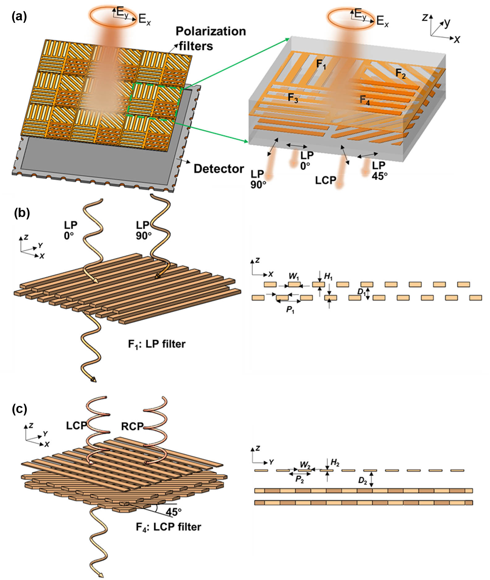
    Fig. 1. Large-area ultracompact pixelated aluminium wire-grid-based metamaterials for full-Stokes polarization imaging. (a) Schematic of the device design for Stokes parameters measurement. F1F3 microcells are linear polarization filters to filter linearly polarized light with the electric field vector oriented at different angles with respect to the x axis, i.e., 0°, 45°, and 90°. F4 microcell is left circular polarization filter to transmit left circular polarization light. (b) Schematic of the linear polarization filters consisting of the double-layer wire-grid. The period, wire width, height, and spacing are P1, W1, H1, and D1, respectively. (c) Schematic of the left circular polarization filter consisting of a top circular–linear polarization converter and an underneath linear polarization filter. The period, wire width, height of the circular–linear polarization converter, and spacing between the circular–linear polarization converter and the linear polarization filter are P2, W3, H2, and D2, respectively.
    Optical parameters of the double-layer nano wire-grid linear polarization filter: (a) TM light transmission, (b) TE light transmission, and (c) linear polarization extinction ratio. Optical parameters of the single-layer nano wire-grid polarization filter: (d) TM light transmission, (e) TE light transmission, and (f) linear polarization extinction ratio. The geometric parameters of the wire-grid are 200 nm period and 100 nm wire width. The spacing between the bilayer wire grids D1=200 nm. Aluminium wire-grid height H1 varies from 10 to 90 nm.
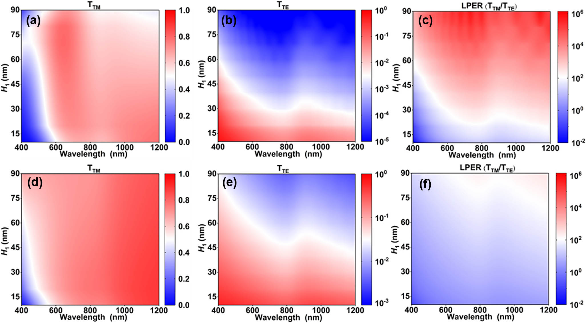
    Fig. 2. Optical parameters of the double-layer nano wire-grid linear polarization filter: (a) TM light transmission, (b) TE light transmission, and (c) linear polarization extinction ratio. Optical parameters of the single-layer nano wire-grid polarization filter: (d) TM light transmission, (e) TE light transmission, and (f) linear polarization extinction ratio. The geometric parameters of the wire-grid are 200 nm period and 100 nm wire width. The spacing between the bilayer wire grids D1=200  nm. Aluminium wire-grid height H1 varies from 10 to 90 nm.
    Simulated optical properties of circular polarization filter with diffrerent D2. (a), (b) Transmittance spectra of LCP and RCP by full-wave (400–1200 nm) simulation. (c), (d) Circular dichroism (CD=TLCP-TRCP) and circular polarization extinction ratio (CPER=TLCP/TRCP) obtained by the transmittance of LCP and RCP.
    Fig. 3. Simulated optical properties of circular polarization filter with diffrerent D2. (a), (b) Transmittance spectra of LCP and RCP by full-wave (400–1200 nm) simulation. (c), (d) Circular dichroism (CD=TLCP-TRCP) and circular polarization extinction ratio (CPER=TLCP/TRCP) obtained by the transmittance of LCP and RCP.
    Device fabrication. (a1) Preparation of IPS flexible template with 0°, 45°, 90°, and −45° orientation wire-grids. (a2) Formation of dielectric wire-grid on the quartz substrate precoated with UV-curable photoresist by UV-curable NIL. (a3) Aluminium wire-grid-based linear polarization filter micro arrays obtained by vertical thermal evaporation process. (b1) Preparation of large-area IPS flexible template with single-directional wire-grid. (b2) Aluminium wire-grid structure obtained by vertical thermal evaporation process. (c1) IPS surface metal nano wire-grid integrated onto the surface of the double-layer metal-aluminum nano wire-grid linear polarization filter micro array precoated with UV-curable photoresist by a nano transfer printing process. (c2) Spin-coating of BP212 on linear polarization filter micro array. (c3) Formation of pixelated metamaterials integrating both the linear polarization filters and circular polarization filters by photolithography, development, etching, and residual adhesive removal process.
    Fig. 4. Device fabrication. (a1) Preparation of IPS flexible template with 0°, 45°, 90°, and 45° orientation wire-grids. (a2) Formation of dielectric wire-grid on the quartz substrate precoated with UV-curable photoresist by UV-curable NIL. (a3) Aluminium wire-grid-based linear polarization filter micro arrays obtained by vertical thermal evaporation process. (b1) Preparation of large-area IPS flexible template with single-directional wire-grid. (b2) Aluminium wire-grid structure obtained by vertical thermal evaporation process. (c1) IPS surface metal nano wire-grid integrated onto the surface of the double-layer metal-aluminum nano wire-grid linear polarization filter micro array precoated with UV-curable photoresist by a nano transfer printing process. (c2) Spin-coating of BP212 on linear polarization filter micro array. (c3) Formation of pixelated metamaterials integrating both the linear polarization filters and circular polarization filters by photolithography, development, etching, and residual adhesive removal process.
    (a1), (a2) SEM surface views of IPS flexible template with 0°, 45°, 90°, and −45° orientation wire-grids. (b) SEM surface view of the UV-curable nanoimprint photoresist patterned with wire-grid structure. (c) SEM surface view of the aluminium nano wire-grids. (d) SEM surface view of the circular linear polarization converter. (e) Polarization micrograph of the prepared sample.
    Fig. 5. (a1), (a2) SEM surface views of IPS flexible template with 0°, 45°, 90°, and 45° orientation wire-grids. (b) SEM surface view of the UV-curable nanoimprint photoresist patterned with wire-grid structure. (c) SEM surface view of the aluminium nano wire-grids. (d) SEM surface view of the circular linear polarization converter. (e) Polarization micrograph of the prepared sample.
    (a) Experimental diagram of the fabricated device measurement system. (b) Example diagram of the imaging system imaging polarized light.
    Fig. 6. (a) Experimental diagram of the fabricated device measurement system. (b) Example diagram of the imaging system imaging polarized light.
    (a), (c) Grayscale value response curves of the three F1–F3 linear polarization filter regions with different azimuthal angles of linear polarization light. (b), (d) Grayscale value response of the F4 circular polarization filter with different chiral circularly polarized light. (a), (b) The filter operates at a wavelength of 810 nm. (c), (d) The filter operates at a wavelength of 740 nm.
    Fig. 7. (a), (c) Grayscale value response curves of the three F1–F3 linear polarization filter regions with different azimuthal angles of linear polarization light. (b), (d) Grayscale value response of the F4 circular polarization filter with different chiral circularly polarized light. (a), (b) The filter operates at a wavelength of 810 nm. (c), (d) The filter operates at a wavelength of 740 nm.
    Testing results of Stokes parameters. The subplots in the left column represent the theoretical and calculated pre-calibration, post-calibration, and post-compensation values of the Stokes parameters S0−S3; the subplots in the right column represent the errors in the calculated pre-calibration, post-calibration, and post-compensation values of the Stokes parameters S0−S3.
    Fig. 8. Testing results of Stokes parameters. The subplots in the left column represent the theoretical and calculated pre-calibration, post-calibration, and post-compensation values of the Stokes parameters S0S3; the subplots in the right column represent the errors in the calculated pre-calibration, post-calibration, and post-compensation values of the Stokes parameters S0S3.
    Polarimetric imaging. (a) Physical image and its corresponding original imaging and polarization state schematic. (b) Calculated Stokes parameter image. (c) Theoretical Stokes parameter image of the targeted polarization mask.
    Fig. 9. Polarimetric imaging. (a) Physical image and its corresponding original imaging and polarization state schematic. (b) Calculated Stokes parameter image. (c) Theoretical Stokes parameter image of the targeted polarization mask.
    ComponentParameterIndex
    Integrating sphereSpectral range350–1100 nm
    Uniformity±1.0%
    SupplierFelles Photonic
    FilterOperating wavelength810 and 740 nm
    Semi-high bandwidth25 nm
    SupplierGiAi
    Linear polarizerExtinction ratio>1000:1
    Transmission>60%
    Wavelength range700–1700 nm
    SupplierEdmund
    Quarter-wave plateOperating wavelength350–850 nm
    SupplierThorlabs
    Precision turntable 1Angle resolution0.01°
    Rotation angle range360°
    SupplierParker Hannifin
    Precision turntable 2Angle resolution0.05°
    Rotation angle range360°
    SupplierAvantes
    Camera lensFocal length8–50 mm
    Format1/2.3
    Relay lensMagnification1:1
    SupplierEdmund
    CameraSensorVendor Sony
    Resolution (H×V)4024  px×3036  px
    Pixel size (H×V)1.85  μm×1  μm
    Table 1. Parameters of Main Components
    Yuanyi Fan, Jinkui Chu, Ran Zhang, Chuanlong Guan, Jianying Liu. Large-area ultracompact pixelated aluminum-wire-grid-based metamaterials for Vis-NIR full-Stokes polarization imaging[J]. Photonics Research, 2023, 11(11): 1975
    Download Citation