Abstract
A new design of total internal reflection (TIR) lens was presented which had a freeform Fresnel surface in the central part of the front to improve the heat dissipation capability. Snell's law and the reflection law were applied to construct the freeform refractive surface and the freeform reflective surface for the TIR lens. The freeform refractive surface was transformed into the freeform Fresnel surface with universal design method of Fresnel lens. The simulation result for the freeform Fresnel TIR lens obtained by Monte Carlo ray tracing shows that the far field illumination uniformity of 82.0% and the luminous efficiency of 96.6% are achieved for the light source size of 2 mm×2 mm, in the meanwhile the lens weight is only 21.94 g. The freeform Fresnel TIR lens has nearly 20% reduction in lens weight and volume, only a 2% reduction in luminous efficiency, and no reduction in illumination uniformity compared to the TIR lens without the Fresnel surface. The result indicates that the Fresnelization for freeform surface of TIR lens can significantly reduce the volume and weight of TIR lens and shorten the optical path length, thus effectively improve its heat dissipation efficiency and service life while maintaining a high performance.0 Introduction
Light-emitting diode (LED) light source characterized by high luminous efficiency, durability and reliability is considered to be the most promising light source of the next generation[1]. LED is close to the theoretical "point source", so it is easy to accurately locate the light source when designing the optical system. However, due to its Lambertian distribution and large divergence angle, it is necessary to redistribute the spatial intensity distribution of a LED, which is called secondary light distribution.
At present, the main light distribution lenses on the market are peanut lens and TIR lens. However, peanut lens has a large size and the poor heat dissipation effect, which reduces its service life as well as increases the cost. Dai Yidan[2] added a gradient Fresnel surface on the peanut lens to reduce the thickness of the lens and improve the heat dissipation efficiency. However, the illumination uniformity is relatively low, only 68%. Zhang Yuebin[3] of Yanshan University proposed heat dissipation method for LED arrays based on water cooling. This method is more effective in reducing the temperature of the LED array, but it will reduce the luminous efficiency and shorten its service life. Sun Lixia of Zhejiang University [4] added a heat sink to the LED light source to improve the heat dissipation efficiency of the lens. However, it has the disadvantage that when the LED light source reaches its service life and need to be replaced, the LED lens is supposed to be redesigned which is very inconvenient. There is also a problem of poor heat dissipation for the TIR lens[5-8] which is commonly used at present. Wan Yunjia[9] of Hubei University proposed a design method of freeform Fresnel lens and designed a thin Fresnel lens with a freeform surface which greatly improve the heat dissipation efficiency. However, the thin Fresnel lens with two transmission surfaces is too simple to achieve a good far field illumination performance. Therefore, the heat dissipation design on the TIR lens is expected to achieve the dual goals of high heat dissipation efficiency and satisfactory far field illumination performance.
The freeform surface can accurately perform the light distribution for the secondary light distribution lens. There are several methods for the design of freeform surfaces: trial and error method[10], numerical analysis method[11-14], and SMS design method (Simultaneous Multiple Surface)[15-17]. The trial and error method require constant modification of parameters thus it is not efficient. The numerical analysis method and the SMS design method can effectively establish the iterative relationship between adjacent sampling points through the numerical relationship, and obtain the discrete point data of the free surface. This method is not only suitable for Lambertian LEDs, but also for non-Lambertian LEDs with wide applicability[18].
In order to improve the heat dissipation efficiency of TIR lens, we designed a freeform TIR lens based on far-field illumination with numerical analysis method, and applied a segmentation method to design a freeform Fresnel TIR lens, then analyzed and compared the far field illumination uniformity, luminous efficiency, lens volume and weight of this two kinds of freeform TIR lens.
1 Design method
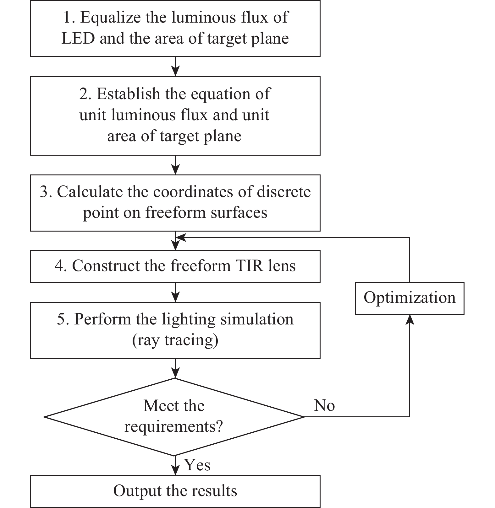
The flow chart for the design of the freeform TIR lens is shown in Fig.1. Step 1 and Step 2 are shown in Section 1.1, mainly to divide the luminous flux of the LED light source and the area of the target plane equally, and establish the equation of unit luminous flux and unit area of the target plane. Step 3 and Step 4 shown in Section 1.2 describes how the freeform TIR lens is designed. The design of the freeform Fresnel surface is accomplished by segmentation method shown in Section 1.3.

Figure 1.Flow chart for designing the freeform TIR lens
1.1 Equalize the luminous flux and the target plane
The luminous intensity distribution of the currently used LED light source is Lambertian distribution. As shown in Fig.2, in order to achieve uniform illumination on the target plane, the illumination angle and the area of the target plane are equally divided[19].
Figure 2.Equalize the luminous flux and the target plane (
: the cone angle of the sampling rays; R: the radius of the target plane;
: the radius of each annulus on target plane)
$ {\int }_{{\theta }_{\rm{i}}}^{{\theta }_{i+1}}{I}_{\theta } \varOmega ={\int }_{{S}_{i}}^{{S}_{i+1}}E{\rm{d}}S $ (1)
where
$ {I}_{\theta } $ is the luminous intensity; and E is the illuminance on the target plane.
The total luminous flux
$ {\varphi }_{\rm{t}} $ of the LED light source is:
$ {\varphi }_{\rm{t}}=2\pi {\int }_{0}^{\frac{\pi }{2}}{I}_{\theta }{\rm{sin}}\theta {\rm{d}}\theta $ (2)
We divide the luminous flux
$ {\varphi }_{\rm{t}} $ of the LED light source into N equal parts:
$ 2{\rm{\pi }}{\int }_{{\theta }_{\rm{i}}}^{{\theta }_{i+1}}{I}_{\theta }{\rm{sin}}\theta {\rm{d}}\theta =\dfrac{{\varphi }_{\rm{t}}}{N}=\dfrac{2\pi }{N}{\int }_{0}^{\frac{\pi }{2}}{I}_{\theta }{\rm{sin}}\theta {\rm{d}}\theta $ (3)
where
$ {\theta }_{{i}} $ is the cone angle of the sampling ray.
We further divide the target plane into N equal-area concentric annulus. The radius of the target plane is R, and the radius of each annulus on target plane is
$ {r}_{i} $. The area
$ {S}_{0} $ of each annulus is:
$ {S}_{0}=\pi {r}_{i+1}^{2}-\pi {{r}}_{i}^{2}=\dfrac{\pi {R}^{2}}{N} \left( {i = 0,1,\;2,\;3,\;\cdots N - 1} \right) $ (4)
The solid angle of the source and the area of the target plane are equally divided based on the Eqs. (1)-(4), thus the directions of the incident ray and the emergent ray are determined.
1.2 Design of freeform TIR lens
The freeform TIR lens has been designed using a numerical analysis method[19]. The cross section schematic diagram of the freeform TIR lens[6] is shown in Fig.3. Surface 1 is a circular plane, surface 2 is a freeform surface to be designed, surface 3 is a cylindrical surface inside, surface 4 is a freeform TIR surface to be designed, and the surface 5 is an annular plane. The LED is placed at the origin of the coordinates (0, 0), where there is a cylindrical cavity inside the TIR lens.
Figure 3.Schematic diagram of the freeform TIR lens (1: a circular plane; 2: a freeform surface to be designed; 3: a cylindrical surface inside; 4: a freeform TIR surface to be designed; 5: an annular plane)
Two freeform surfaces of the TIR lens is solved by the Snell's law and the reflection law, respectively. The freeform refractive surface 2 of the TIR lens is solved by the Snell's law:
$ {\left[1+{n}^{2}-2n\left({{O}} \cdot {{I}}\right)\right]}^{1/2} \cdot {{N}}={{O}}-n{{I}} $ (5)
The freeform reflective surface 4 of the TIR lens is solved by the reflection law:
$ \sqrt{2-2\left({{O}} \cdot {{I}}\right)} \cdot {{N}}={{O}}-{{I}} $ (6)
A. Freeform refractive surface design
The rays emitted from the point O (LED source) with small spread angles will be collimated by the freeform refractive surface. A series of sampled rays are taken at equal angular intervals as shown in Fig.4(a). The coordinates of the points on plane
$ {S}_{1} $ is
$ {e}_{i+1}({x}_{1i+1},{y}_{1i+1}) $[18]:
Figure 4.Optical geometry of freeform surface
$ {y}_{1i+1}=h $ (7)
$ {x}_{1i+1}=h×\tan\left({A}_{i+1}\right) $ (8)
Constructing the freeform refractive surface
$ {S}_{2} $ is the process of calculating the coordinates of the points
$ {E}_{1} $,
$ {E}_{2} $,···,
$ {E}_{i} $. The main iteration between two adjacent sampling points
$ {E}_{i}({x}_{2i},{y}_{2i}) $ and
$ {E}_{i+1}({x}_{2i+1},{y}_{2i+1}) $ on
$ {S}_{2} $ is derived by using Snell's law as shown in Eqs. (9)-(10):
$ {x}_{2i+1}=\dfrac{{y}_{2i}-{y}_{1i+1}+{\rm{cot}}\left({P}_{i+1}\right){x}_{1i+1}-{k}_{2i}{x}_{2i}}{{\rm{cot}}\left({P}_{i+1}\right)-{k}_{2i}} $ (9)
$ $ (10)
where
$ {k}_{2i} $ is the tangent slope of the freeform surface
$ {S}_{2} $ at
$ {E}_{i} $:
$ {k}_{2i}=\dfrac{\dfrac{{(x}_{4i}-{x}_{2i})}{\sqrt{{({x}_{4i}-{x}_{2i})}^{2}+{({y}_{4i}-{y}_{2i})}^{2}}}-\dfrac{n({x}_{2i}-{x}_{1i})}{\sqrt{{{x}_{2i}}^{2}+{{y}_{2i}}^{2}}}}{\dfrac{n({y}_{2i}-{y}_{1i})}{\sqrt{{{x}_{2i}}^{2}+{{y}_{2i}}^{2}}}-\dfrac{({y}_{4i}-{y}_{2i})}{\sqrt{{({x}_{4i}-{x}_{2i})}^{2}+{({y}_{4i}-{y}_{2i})}^{2}}}} $ (11)
If the initial point
$ {E}_{i} $ is known, the coordinates of all points on the surface
$ {S}_{2} $ can be calculated using the iterative Eqs. (9)-(10).
B. Freeform TIR surface design
As shown in Fig.4(b), the rays emitted from the point O (LED source) with large spread angles first travel through the vertical plane surface
$ {S}_{3} $, then hit the TIR surface
$ {S}_{4} $ being reflected, and are finally redirected parallel to the y-axis through the horizontal plane surface
$ {S}_{5} $. The points on surface
$ {S}_{3} $ is
$ {F}_{t}({x}_{3,t},{y}_{3,t}) $, and the points on surface
$ {S}_{4} $ is
$ {f}_{t}({x}_{4,t},{y}_{4,t}) $. The iteration for two adjacent sampling points
$ {f}_{t}({x}_{4,t},{y}_{4,t}) $ and
$ {f}_{t+1}({x}_{4,t+1},{y}_{4,t+1}) $ on the surface
$ {S}_{4} $ is as follows[18]:
$ {x}_{4,t+1}=\dfrac{{-y}_{4,t}+{y}_{3,t+1}-{m}_{3,t+1}{x}_{3,t+1}+{p}_{4,t}{x}_{4,t}}{{p}_{4,t}-{m}_{3,t+1}} $ (12)
$ {y}_{4,t+1}={p}_{4,t}\left({x}_{4,t+1}-{x}_{4,t}\right)+{y}_{4,t} $ (13)
where
$ {m}_{3,t+1} $ is the slope of
$ {F}_{t+1}{f}_{t+1} $, and
$ {p}_{4,t} $ is the slope of the tangent at the point
$ {f}_{t} $:
$ {m}_{3,t+1}=\dfrac{{y}_{4,t+1}-{y}_{3,t+1}}{{x}_{4,t+1}-{x}_{3,t+1}} $ (14)
$ {p}_{4,t}=\dfrac{\dfrac{({x}_{4,t}-{x}_{3,t})}{\sqrt{{({x}_{4,t}-{x}_{3,t})}^{2}+{({y}_{4,t}-{y}_{3,t})}^{2}}}}{\dfrac{({y}_{4,t}-{y}_{3,t})}{\sqrt{{({x}_{4,t}-{x}_{3,t})}^{2}+{({y}_{4,t}-{y}_{3,t})}^{2}}}} $ (15)
Thus, the coordinates of all points on the surface
$ {S}_{4} $ can be obtained using the iterative Eqs. (12)-(13) to construct freeform TIR surface
$ {S}_{4}. $
1.3 Freeform Fresnel surface design with the segmentation method
After designing the freeform TIR lens, we use the segmentation method[9] to perform Fresnelization on the freeform surface
$ {S}_{2} $. Figure 5 shows a Fresnel surface. Assuming that the refractive index of the lens material is uniform, the Fresnel lens maintains the curvature of the lens surface and the direction of the ray does not change while the excess material of the lens being removed.
Figure 5.Schematic diagram of Fresnel lens (R: the half-diameter of the lens; d: the width of each annulus;
: the half inside-diameter of the jth Fresnel annulus;
the half outer-diameter of the jth Fresnel annulus)
The half-diameter of the lens is defined as R, and the surface of the lens is divided into N equal annulus, and the width of each annulus is d, then d=R/N. The half-diameter of the target plane is L which is also divided into N equal annulus, then the width of each annulus is w=L/N. The incident light on the jth Fresnel annulus of the lens is required to arrive at the jth annulus of the target plane, which does not guarantee that the illumination distribution on the target plane is uniform. Thus, each Fresnel annular zone of the lens should continue to be subdivided. As shown in Fig.5, the width of the jth Fresnel annular zone between the
$ {R}_{j} $ and the
$ {R}_{j+1} $ is:
$ \Delta R={R}_{j+1}-{R}_{j}=d(0\leqslant j\leqslant N) $ (16)
When the Fresnel annular zone is divided into M parts at equal space, the width of each part is:
$ \Delta r=d/M $ (17)
The radius
$ {R}_{j} $ can be expressed as:
$ {R}_{j}= j\times d $ (18)
In this way, the radius
$ {{r}}_{ji} $ of each equidistant points on the jth annulus is:
$ {r}_{ji}={R}_{j}+i\Delta r(0\leqslant i \leqslant M) $ (19)
The jth annulus of the target plane can also be equally divided in the same way, and the radius of each equidistant points is
$ {t}_{ji} $. The incident light on the
$ {{r}}_{ji} $ and
$ {r}_{ji+1} $ regions of jth Fresnel annular zone is controlled to arrive on the
$ {t}_{ji} $ and
$ {t}_{ji+1} $ region of the target plane
$ {S}_{6} $, where
$ {r}_{ji} $ is equivalent to the discrete point coordinate
$ {E}_{i} $ on the freeform surface
$ {S}_{2} $ in section 1.2, and
$ {t}_{ji} $ is equivalent to
$ {M}_{i} $ on the target plane
$ {S}_{6} $. The ordinate
$ {y}_{2i} $ of each point
$ {E}_{i} $ is simultaneously reduced by a height h, and the abscissa
$ {x}_{2i} $ remains unchanged. This produces a uniform illuminance distribution on the target plane.
2 Simulation and analysis
The freeform TIR lens is designed using the method described in the section 1.2, and the lighting simulation (ray tracing) is performed. In order to improve the illumination performance of the freeform TIR lens, we reduce the area of the target region where the illuminance value is relatively large, and enlarge the area of the target region where the illuminance value is relatively small using the inverse feedback optimization method. The overall illuminance uniformity is improved, and the cross-section diagram is shown in Fig.6(a), and the illuminance distribution is shown in Fig.7(a). Then the freeform surface
$ {S}_{2} $ is Fresnelized. The main parameters of the Fresnel lens are summarized in Tab.1. CREE XLamp XR-E series is selected as the light source. The luminous flux is 100 lm, the divergence angle is 170°, and the surface light source size is 2 mm×2 mm; the target plane is 10 m away from the light source, and half-diameter of the target plane is 2.5 m. In order to further improve the optical illumination effect, the freeform Fresnel TIR lens with different number of segments is optically simulated. The simulation results are shown in Tab.2. When the number of segments is larger, the illumination effect is better, but the manufacturability gets worse. As a tradeoff, the number of segments N is defined as 22 in our work. The 2D cross-section diagram is shown in Fig.6(b), and the illuminance distribution is shown in Fig.7(b). The height of the freeform TIR lens without the Fresnel surface is 8.60 mm, and the height of the freeform TIR lens with the Fresnel surface is 1.08 mm, which decreases by 7.52 mm.
| Parameter | Specification |
| Light source size/mm | 2×2 |
| Half-diameter of the lens/mm | 24 |
| Half-diameter of the target plane/m | 2.5 |
| Distance between target plane/m and the light source/m | 10 |
| Lens material | PMMA |
| Number of segments N | 22 |
Table 1. Main parameters of Fresnel lens
| Number of segments N | 16 | 18 | 20 | 22 |
| Illumination uniformity | 72.3% | 75.4% | 78.1% | 82.0% |
| luminous efficiency | 89.2% | 92.3% | 93.3% | 96.6% |
Table 2. Illumination effect of freeform Fresnel TIR lenses with different numbers of segments
Figure 6.2D cross-section diagram of two types of TIR lens
Figure 7.Illuminance distribution of two types of TIR lens
According to the illuminance distribution diagram, the illuminance uniformity of the two lenses is obtained according to the uniformity calculation shown in Eq. (20):
$ {{U}}=\dfrac{{E}_{{\rm{max}}}+{E}_{\min}}{2\cdot {E}_{{\rm{max}}}}=\dfrac{1}{2}+\dfrac{{E}_{\min}}{{2\cdot E}_{{\rm{max}}}} $ (20)
The luminous efficiency values given by the software are listed in Tab.3. The corresponding weight, volume and superficial area of the two lenses are listed in Tab.3. The 3-D structure diagrams of the freeform TIR lens is shown in Fig.8(a) and the freeform Fresnel TIR lens is shown in Fig.8(b).
| Volume/mm3 | Weight/g | Superficial area/mm2 | Illumination uniformity | Luminous efficiency |
| Freeform TIR lens | 27437.27 | 27.44 | 5977.53 | 82.0% | 98.2% |
| Freeform TIR Fresnel lens | 21940.06 | 21.94 | 5899.18 | 82.0% | 96.6% |
Table 3. Comparison of lens size and illumination performance
Figure 8.3D models of two types of TIR lens
It can be seen from Fig.7 and Tab.3 that the far field illumination uniformity of both two TIR lenses is 82.0%, indicating that the original illumination performance is maintained. The luminous efficiency of the freeform TIR lens with Fresnel surface slightly decreased from 98.2% to 96.6%, but it still maintained a high level. The TIR lens with Fresnel surface is reduced by about 20% in volume and weight compared with the TIR lens without the Fresnel surface. This shows that the Fresnelization of freeform refractive surface of the freeform TIR lens can significantly reduce the volume and weight of the lens and shorten the optical path length, thus effectively improving the heat dissipation efficiency and service life of the lens, while maintaining the original illumination uniformity.
3 Conclusion
In this article, a freeform TIR lens is designed based on Snell's law and reflective laws, and a freeform Fresnel TIR lens is designed by segmenting the freeform surface. The freeform Fresnel TIR lens has nearly 20% reduction in lens weight and volume compared with the TIR lens without Fresnel surface. The optical path length is shortened, thereby the heat dissipation efficiency of the lens is improved. In terms of optical properties, the freeform Fresnel TIR lens has high illumination uniformity and high luminous efficiency, so the LED light source can be fully used and it is beneficial to the secondary energy saving.
References
[10] E Aslanov, L L Doskolovich, M A Moiseev. Thin LED collimator with free-form lens array for illumination applications. Applied Optics, 51, 7200(2012).