• Acta Physica Sinica
  • Vol. 69, Issue 13, 134202-1 (2020)
Bao-Jing Hu1、2, Ming Huang1、*, Peng Li1, and Cheng-Fu Yang1
Author Affiliations
  • 1School of Information Science and Engineering, Yunnan University, Kunming 650091, China
  • 2College of Science, Yunnan Agricultural University, Kunming 650201, China
  • show less
    DOI: 10.7498/aps.69.20200093 Cite this Article
    Bao-Jing Hu, Ming Huang, Peng Li, Cheng-Fu Yang. Multiband plasmon-induced transparency based on silver nanorods and nanodisk hybrid model[J]. Acta Physica Sinica, 2020, 69(13): 134202-1 Copy Citation Text show less
    Schematic diagrams of dual-band PIT model: (a) Three-dimensional space schematic; (b) two-dimensional plane schematic.
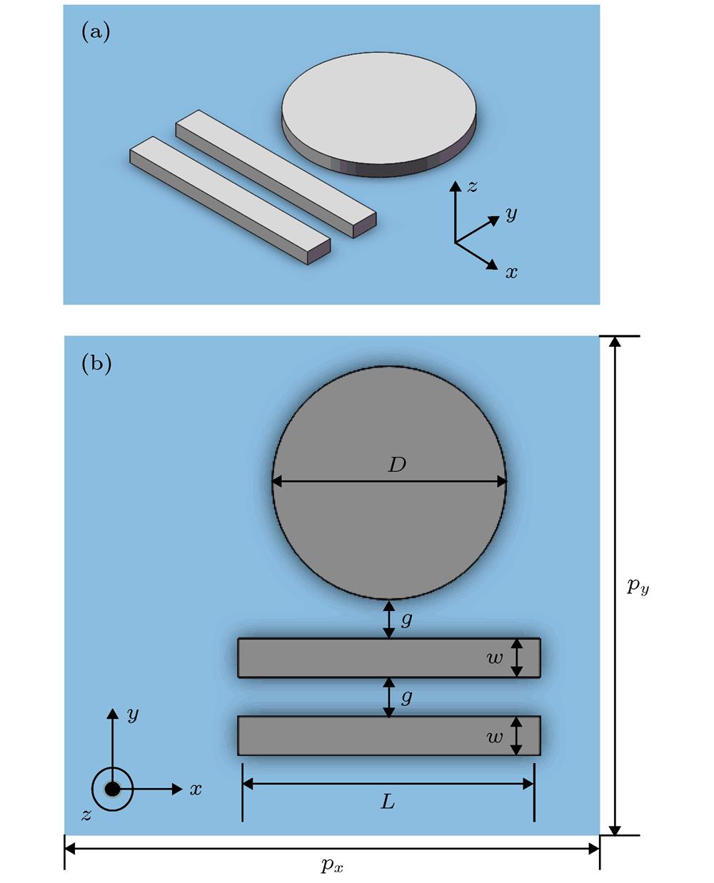
    Fig. 1. Schematic diagrams of dual-band PIT model: (a) Three-dimensional space schematic; (b) two-dimensional plane schematic.
    Transmission spectra of the sole nanodisk array, the sole nanorod array, the single-band PIT model
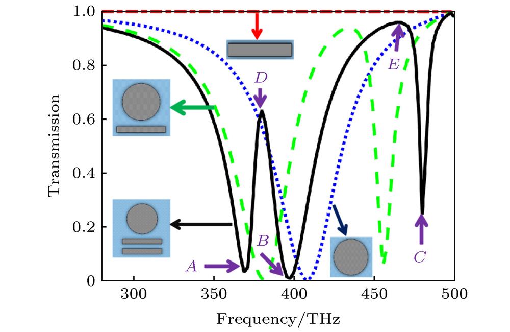
    Fig. 2. Transmission spectra of the sole nanodisk array, the sole nanorod array, the single-band PIT model
    Distribution of electric field of dual-band PIT model at (a) dip A, (b) dip B, (c) dip C, (d) peak D and (e) peak E.and the dual-band PIT model.
    Fig. 3. Distribution of electric field of dual-band PIT model at (a) dip A, (b) dip B, (c) dip C, (d) peak D and (e) peak E.and the dual-band PIT model.
    Variation of transmission with frequency of different g.
    Fig. 4. Variation of transmission with frequency of different g.
    Variation of transmission with frequency of different L
    Fig. 5. Variation of transmission with frequency of different L
    Schematic diagrams of four-band PIT model: (a) Three-dimensional space schematic; (b) two-dimensional plane schematic.
    Fig. 6. Schematic diagrams of four-band PIT model: (a) Three-dimensional space schematic; (b) two-dimensional plane schematic.
    The transmission of four-band PIT model.
    Fig. 7. The transmission of four-band PIT model.
    The comparison of transmission between two dual-band PIT models and four-band PIT model.
    Fig. 8. The comparison of transmission between two dual-band PIT models and four-band PIT model.
    Distribution of electric field of four-band PIT model at (a) peak A, (b) peak B, (c) peakC, (d) peak D.
    Fig. 9. Distribution of electric field of four-band PIT model at (a) peak A, (b) peak B, (c) peakC, (d) peak D.
    Variation of transmission with frequency of different L2.
    Fig. 10. Variation of transmission with frequency of different L2.
    Variation of transmission with frequency of different L1.
    Fig. 11. Variation of transmission with frequency of different L1.
    Variation of transmission with frequency of different g.
    Fig. 12. Variation of transmission with frequency of different g.
    The variation of transmission windows with different background materials.
    Fig. 13. The variation of transmission windows with different background materials.
    The variation of peak A and peak B with different background materials.
    Fig. 14. The variation of peak A and peak B with different background materials.
    The variation of peak C and peak D with different background materials.
    Fig. 15. The variation of peak C and peak D with different background materials.
    传感器类型FOM/RIU–1参考文献
    太赫兹超灵敏超材料传感器2.30[24]
    双分离环对混合传感器2.86[25]
    圆形、方形分离环混合传感器7.80[26]
    金属纳米孔阵列传感器10.5[27]
    双频段太赫兹超材料传感器24.6[28]
    四频段银棒、银盘混合传感器26.4本文
    Table 1. Comparison of FOM with reported sensor in different references.
    Bao-Jing Hu, Ming Huang, Peng Li, Cheng-Fu Yang. Multiband plasmon-induced transparency based on silver nanorods and nanodisk hybrid model[J]. Acta Physica Sinica, 2020, 69(13): 134202-1
    Download Citation