1Nanophotonics Research Centre, Shenzhen Key Laboratory of Micro-Scale Optical Information Technology, Shenzhen University, Shenzhen 518060, China
2Department of Electronic Engineering, Jinan University, Guangzhou 510632, China
3Department of Physics, Capital Normal University, Beijing Key Laboratory of Metamaterials and Devices, Key Laboratory of Terahertz Optoelectronics, Ministry of Education, and Beijing Advanced Innovation Center for Imaging Technology, Beijing 100048, China
4State Key Laboratory of Optoelectronic Materials and Technologies and School of Electronics and Information Technology, Sun Yat-sen University, Guangzhou 510275, China
The quickly increasing data transfer load requires an urgent revolution in current optical communication. Orbital angular momentum (OAM) multiplexing is a potential candidate with its ability to considerably enhance the capacity of communication. However, the lack of a compact, efficient, and integrated OAM (de)multiplexer prevents it from being widely applied. By attaching vortex gratings onto the facets of a few-mode fiber, we demonstrate an integrated fiber-based OAM (de)multiplexer. A vortex grating fabricated on the fiber facet enables the direct multiplexing of OAM states at one port and the demultiplexing of OAM states at the other port. The measured bit error rate of the carrier signal after propagating through a 5-km few-mode fiber confirms the validity and effectiveness of the proposed approach. The scheme offers advantages in future high-capacity OAM communication based on optical fiber.
The demand for high-capacity, high-density data transfer has emerged along with the developing information industry, which eagerly awaits a revolution in current optical communication techniques. The traditional optical communication multiplexing resources, such as amplitude, phase, polarization, and wavelength division multiplexing [1–3], will become exhausted in the near future. Researchers have mitigated this problem by introducing mode division multiplexing to optical communication. Optical vortices are modes with intrinsic orbital angular momentum (OAM). OAM states are inherently orthogonal to each other and can potentially dramatically increase the capacity of optical communication. OAM communication has attracted the attention of many researchers over the past decade [3–7]. Among the major advances reported in recent years, two major scenarios for OAM multiplexing optical communication stand out: free-space [8–10] and fiber [1,11,12] communication. The free-space-based OAM multiplexing is suitable for applications with weak atmospheric turbulence, such as satellite to satellite communication in outer space. Fiber-based OAM multiplexing is suitable for short distance communication in a complex environment, such as intra-datacenters in the future. In these facilities, the fiber-based OAM communication system has better stability in a turbulent atmosphere compared with free-space OAM communication. However, the lack of compact and efficient OAM (de)multiplexing devices is a big obstacle for practical OAM fiber communication applications.
In the past few years, some developments have been made in OAM (de)multiplexing. The spiral phase plates or interferograms were first used to generate and detect a single OAM mode [13–16]. For free-space OAM communication, the spatial light modulator and beam splitter are used to enable OAM (de)multiplexing [9]. The Dammann grating was developed to detect (or generate) multiple OAM states simultaneously [17–19]. The Dammann grating is widely used in OAM communication and significantly increases the number of the multiplexing OAM states, which greatly enhances the communications capacity [8,20]. The major limitation of the Dammann grating is its relatively low efficiency, which is inversely proportional to the number of multiplexing OAM modes. To further improve the efficiency, Gregorius et al. described an approach for OAM sorting based on a geometric transformation with near-perfect efficiency [21–23]. Although this approach seems ideal for free-space OAM (de)multiplexing, it is difficult to align the separated optical elements in a fiber-based optical communication system. To find a compact and integrated solution, researchers have reported a few approaches based on metasurfaces [24–26]. However, their extremely low efficiency and complex manufacturing hinder further practical applications. With the development of micro/nano-fabrication, very compact and complex structures, such as three-dimensional (3D) Raman sensors [27], fiber microphones [28], micro-beam shapers, and micro-imaging lenses [29–31], can be fabricated on facets of an optical fiber. These fabrication techniques make it possible to attach OAM (de)multiplexers. However, to date, there has been no reported demonstration of an integrated fiber-based OAM communication.
Inspired by the concept of “lab-on-fiber,” we design and demonstrate an integrated fiber-based OAM (de)multiplexer, which is composed of a polymer vortex grating and a few-mode optical fiber. The concept is that we use the fiber tip as a platform, and then attach the OAM (de)multiplexer onto the fiber facet using micro/nano-fabrication. The designed optical vortex grating enables the direct conversion of multiple Gaussian beams to multiple OAM states of different orders within the optical fiber. After coaxial propagation, these OAM modes are converted back to Gaussian-like beams in different directions. Here the core element is the micro/nano-fabricated vortex grating. The vortex grating is fabricated on the fiber facet using 3D femtosecond laser direct writing (fabrication details are given in the Appendices A and B). Given by the limited number of OAM modes supported in the used few-mode fiber, we demonstrate (de)multiplexing of two OAM states of orders and . The excitation and evolution of the OAM states are investigated using 3D finite-difference time domain (FDTD) simulations. The quality of the OAM states is also examined by monitoring its intensity and phase profile with interferometry. Finally, the bit error rate (BER) of the OAM communications is characterized after a 5-km-long propagation in the few-mode fiber with a facet-integrated (de)multiplexer.
Sign up for Photonics Research TOC. Get the latest issue of Photonics Research delivered right to you!Sign up now
2. PRINCIPLE AND SIMULATION
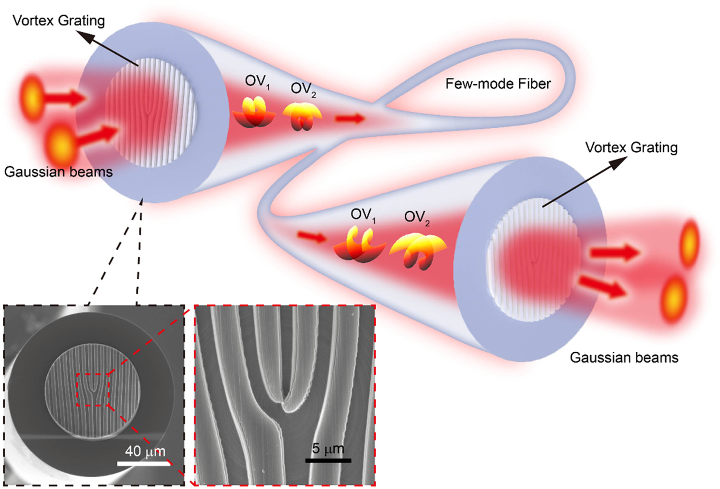
Figure 1 shows a schematic of an integrated optical vortex grating on the few-mode fiber facet. The optical vortex grating or fork grating is a widely used element for OAM beams multiplexing and demultiplexing. With incident OAM beams of orders and , the optical vortex grating converts them to Gaussian-like beams in the and diffraction directions. Through the inverse process, the incident Gaussian beams with corresponding incident angles are converted to coaxial optical vortex beams carrying and -order OAM modes. Therefore, the optical vortex grating integrated on the fiber facet couples the multiple input Gaussian beams to fiber-guided OAM modes. The orthogonal OAM modes propagate coaxially in the few-mode fiber and convert back to Gaussian beams with corresponding diffraction directions by passing through an identical optical vortex grating. The inset in Fig. 1 shows scanning electron microscope (SEM) images of the fabricated grating on the fiber facet. The few-mode fiber has a core diameter of 20 µm and supports the first- and second-order OAM modes. To match the dimension of the fiber core, the designed grating has a circular shape with a radius of 30 µm and a period of 6 µm. The Dammann grating design is implemented to suppress high-order diffractions.
Figure 1.Schematic of an all fiber OAM communication system based on the integrated (de)multiplexer. Through the multiplexing grating, the incident Gaussian beams are converted to optical vortex beams carrying OAM states. After propagation in the few-mode fiber, the coaxial OAM beams are demultiplexed to Gaussian beams by an identical grating at the output facet of the fiber.
For the normal incident light beam, the diffraction angle of the vortex grating is around 18° given by the grating period. Therefore, we chose an incident angle for the Gaussian beams at around 18° relative to the facet normal direction. Figure 2 presents the simulation results of the incident Gaussian beams to the fiber-guided OAM modes conversion. Mode purity is defined by the ratio of the desired OAM-mode power to the total power guided in the fiber. From a 3D FDTD simulation, Fig. 2(a) shows the mode purity for the order OAM beam with a coupling angle from to . At , the mode purity reaches its maximum value and decreases to with a 2° misalignment. For the order OAM mode [Fig. 2(b)], a similar trend in mode purity is observed at different coupling angles. In Fig. 2(c), we simulated the coupling efficiency of the two OAM modes from the incident Gaussian beams at the optimized coupling angles of and . The coupling efficiency of the OAM beams is also related to the numerical aperture (NA) of the incident beam. With increasing NA, the efficiency drops from 95% to because of significant NA mismatch between the few-mode fiber and the beam. However, in this work, limited by the experimental setup, we used a relatively high NA (0.4) objective lens for the light beam coupling. Therefore, there is room to further improve the performance of the OAM beams multiplexing system (see Appendices A and B, Section 2).
Figure 2.Simulated mode purity of (a) and (b) order OAM beams converted from incident Gaussian beams at various coupling angles. (c) Simulated coupling efficiency for the (black) and (red) OAM modes with various numerical apertures.
To investigate the Gaussian beam-to-OAM mode evolution in the fiber, we simulate the beam propagation and conversion by a vortex grating on the input facet of a few-mode fiber using 3D FDTD (Fig. 3). Cross sections of the -order OAM mode fields and phase distributions in the and planes were developed. The plane is the transverse plane of the light beam, and the axis is the direction of light propagation. In Fig. 3(a), the mode distributions at the positions of , 150 µm, 250 µm, and 400 µm away from the fiber facet are presented. Figure 3(b) provides the corresponding phase profiles. In the 50-µm plane from the facet, neither the intensity nor phase of the typical OAM beams is formed. In the 150-µm plane, a donut-shaped beam profile is observed with a zero-order beam in the cladding layer. The corresponding phase profile shows a clear two-cycle phase change from 0 to , indicating a -order OAM mode. When the light beam has propagated 150 µm in the fiber, the modes of other orders of the beams have leaked out, and only the desired OAM beam is well preserved. The intensity and phase profiles of the OAM mode are further purified after propagation for 400 µm and become stable. Similarly, Figs. 3(c) and 3(d) show the excitation and evolution of the order OAM mode in the fiber. Multiplexing of the OAM modes has thus been demonstrated within a section of fiber of several hundred micrometers.
Figure 3.FDTD simulation of the excitation and evolution of OAM modes with an integrated multiplexer on the fiber facet. (a) Intensity and (b) phase excitation and evolution of the OAM mode of order . Corresponding (c) intensity and (d) phase of the -order OAM mode.
Figure 4(a) illustrates the experimental setup of an OAM multiplexing communication system enabled by integrated vortex gratings. The laser beam at 1550-nm wavelength is modulated and encoded using an arbitrary-waveform generator with 23.8-Gbit/s data rate. Through an erbium-doped fiber amplifier (EDFA) and a 3-dB coupler, the input signal is amplified and divided into two branches. After sectioning with fibers of 20-m length difference, the two Gaussian beams carrying decorrelated signals are collimated with appropriately adjusted circular polarization states. The two Gaussian beams are incident on a objective lens at specific angles to ensure that the focused beams are incident on the vortex grating at the designed coupling angles. Passing through the vortex grating integrated on the facet, the two Gaussian beams are multiplexed into OAM beams of orders and then coaxially propagate in a 5-km few-mode fiber. At the receiver end, another integrated vortex grating like that at the multiplexer converts the OAM beams to high-intensity spots at the corresponding diffraction angles. We use two single-mode fibers to collect the transmitted signals from the OAM channels. Passing subsequently an attenuator, band-pass filter, and EDFA, the signals are detected by a photodetector, and the BER performance is characterized using an oscilloscope. Figures 4(b) and 4(c) show the intensity and interference patterns of the -order OAM beam after beam conversion by the integrated vortex grating. Figures 4(d) and 4(e) show similar patterns of the -order OAM beam. The spiral patterns in Figs. 4(c) and 4(e) indicate the OAM states.
Figure 4.Experimental setup of the OAM multiplexing fiber communication system. (a) Experimental setup comprises a transmitter, OAM (de)multiplexer, and receiver. The inserts show the measured intensity of the incident Gaussian beam, the generated OAM mode, and the two demultiplexed Gaussian beams, respectively. PC: polarization controller; SMF: single-mode fiber; EDFA: erbium-doped fiber amplifier; AWG: arbitrary-waveform generator; MZM: Mach–Zehnder electro-optical modulator; VOA: variable optical attenuator; BPF: band-pass filter; PD: photodiode; OSC: oscilloscope. (b) and (c) are the measured intensity and interferograms, respectively, for the generated -order OAM mode. (d) and (e) are the corresponding measured results for the -order OAM mode.
Figure 5 shows the experimental results of the OAM multiplexing fiber communication system. Figures 5(a)–5(c) show the demultiplexing of the OAM beam, OAM beam, and the coaxial OAM beams by the grating after the 5-km propagation in the fiber. The grating converts the OAM beams to high intensity spots in the corresponding diffraction directions. Theoretically, the two multiplexing OAM modes are orthogonal to each other; thus, there should not be any crosstalk. However, in practice, there is some crosstalk due to the bending, twisting, and imperfection of the few-mode fiber. The crosstalk of the OAM modes in the fiber can be minimized by implementing a polarization controller in the experiment setup. In the experiment, the measured crosstalk is less than for both the two OAM modes after 5-km propagation in the few-mode fiber. The total loss of the communication system is about 24 dB, mainly caused by the objective lenses. Since the objective lenses are coated for the visible light, the loss for the telecom band is 5–6 dB. Thus, there is still 10–12 dB loss that could be saved by optimizing the two objective lenses. The coupling loss of the integrated multiplexer/demultiplexer (vortex grating) is measured as about 3.2 dB and 3.3 dB, respectively. The propagation loss of the 5 km few-mode fiber for OAM modes is about 2 dB. The other loss is caused by the mismatch of the NA between the fiber and the objective, which could also be significantly reduced by using low NA objectives. The BER of the signals carried by the OAM channel and the multiplexing OAM channels was measured [Fig. 5(d)]. The back-to-back signals (black) are shown along with the OAM-mode-carrier signals without (red) and with (blue) multiplexing and the OAM-mode-carrier signals without (purple) and with (green) multiplexing. For the OAM mode, the BER curves almost overlap with the back-to-back curve, indicating good signal quality and low mode crosstalk. For the OAM mode, the BER curve shows a 2.6-dB power penalty at the forward error correction threshold of that may have been induced by a relative difference in the two OAM-mode generation or demultiplexing efficiency.
Figure 5.Experimental results of OAM multiplexing fiber communication using integrated vortex grating. Demultiplexing results of (a) mode, (b) mode, (c) and modes. (d) Measured bit error rate (BER) of the OAM communication system.
Limited by the number of modes supported in the few-mode fiber we used, we demonstrated only two OAM modes multiplexing. In fibers supporting higher-order OAM modes, there is no fundamental limit to further increase the number of multiplexing OAM modes to several tens by using vortex gratings.
4. CONCLUSIONS
We proposed and demonstrated an integrated vortex-grating-based OAM-multiplexing fiber communications system. Vortex gratings fabricated on the facets of a few-mode fiber enabled all-fiber OAM-multiplexing/demultiplexing functionality. The FDTD simulation showed that the Gaussian beams incident onto the grating evolve into OAM modes after hundreds of microns propagation in the few-mode fiber. Both the intensity and phase profiles guarantee high mode purity of up to 99% () for the generated OAM modes. In the experiment, we converted two free-space Gaussian beams guided into the fiber at designed incident angles to and -order OAM beams using the vortex grating. We also demonstrated OAM-multiplexing fiber communications over a 5-km few-mode fiber using a pair of integrated vortex gratings as multiplexer and demultiplexer. BER measurements indicated good performance of this OAM multiplexing system. In addition to being ultra-compact in size and low cost to make, the integrated fiber OAM (de)multiplexer also provides efficiency, flexibility, and wide broadband response. Therefore, it has promising applications in optical fiber-based high-capacity OAM communications.
Acknowledgment
Acknowledgment. X. Yuan appreciates the support given by the Leading Talents Program of Guangdong Province.
APPENDIX A. VORTEX GRATING DESIGN AND FABRICATION
We design and fabricate a polymer vortex grating enclosed in a circle area with 60 μm radius. The period of the grating is chosen as 6 μm to obtain the proper diffraction angle. The pure phase distribution of the grating is described as where and are the total number of the diffraction orders (a positive integer) along the axis and axis, respectively, is the period of the grating, , are the diffraction orders along the axis and axis, respectively, is the azimuthal angle, and is the diffraction order, which is a non-zero integer. is the power of the diffraction order normalized with respect to the total power. According to Eq. (A1), we designed a 2-by-1 vortex grating with two diffraction orders in the axis. We set the order interval to 2 for the axis. Consequently, this designed grating comprising two diffraction orders can generate or detect two optical vortices with OAM orders of and . The phase distribution is transferred to the height of the polymer grating using the following equation: where is the height of the polymer grating, is the phase distribution of the vortex grating, is the wavelength of 1550 nm for the telecom band, and is the refractive index of the polymer, which is 1.45 for the photoresist (IP-L, Nanoscribe GmbH).
Figure 6 shows schematics of the fabrication used in making the vortex grating on the facet of an optical fiber. The setup [Fig. 6(a)] allows one to overcome the difficulties of 3D micro- and nano-structuring by two-photon lithography on the facets. The cleaved facet of the optical fiber serves as the platform for the OAM (de)multiplexer. A few-mode optical fiber with a core diameter of 20 μm and a cladding of 125 μm in diameter was used. A thin microscope coverslip with a thickness of 170 μm is inserted between the facet and the objective lens. Both the fiber and the coverslip are put into a holder that allows the distance between facet and coverslip to be adjusted with micrometer precision. A photoresist is deposited on top of the coverslip to fill up the gap between the facet and the coverslip. Optical matching oil is inserted between the coverslip and the objective lens. A 3D lithography system (Photonic Professional GT, Nanoscribe GmbH) was employed to perform the writing process of the vortex grating on the facet. During the process, a computer-controlled sample stage is used to precisely manipulate the position of the laser focus with respect to the fiber facet. The model of the vortex grating is as defined in Eq. (A2) using a solid modeling computer-aided design software (SolidWorks, Dassault Systèmes). The 3D design is afterwards translated into a code compatible with the control software of the lithography system. Based on this code, the lithography system transfers the designed structure into the photoresists using a digital writing process (Fig. 6).
Figure 6.Image showing the fabrication of a vortex grating on the facet of a few-mode fiber using two-photon lithography. (a) Fiber holder used to adjust and to fix the position of the fiber tip with respect to the 3D writing system. (b) Schematic of the geometrical arrangement of the few-mode fiber, photoresist, glass slide, optical matching oil, and objective lens during 3D writing using two-photon lithography.
APPENDIX B. COUPLING EFFICIENCY OF THE OAM (DE)MULTIPLEXER
The OAM-beam coupling efficiency is also related to the NA of the incident beam. With increasing NA of the incident light beam, the coupling efficiency drops from 95% to because of a significant NA mismatch between the fiber and beam (Fig. 7). However, for the experimental setup in this work, we use a relatively high NA objective lens to couple the two OAM states at the same time. Therefore, there is still room to further improve the performance of the OAM-beam multiplexing system. Nevertheless, we investigated the coupling efficiency of a single OAM mode with different objective lenses, , , , , and . The waist of the incident beam is 3 mm in diameter, and the entrance pupil is various with respect to the objective lens. Therefore, the effective NAs of the objective lenses are calculated as 0.03633, 0.07707, 0.15343, 0.26223, and 0.41452, respectively. The corresponding measured results illustrated in Fig. 7 are consistent with the FDTD simulations.
Figure 7.Coupling efficiency for the OAM mode as a function of numerical aperture obtained from FDTD simulations (red) and from measurements (cyan).