1School of Physics and Optoelectronic Engineering, Ludong University, Yantai 264025, China
2Engineering Research Center of Optical Instruments and Systems, Ministry of Education, Shanghai Key Lab of Modern Optical Systems, School of Optical-Electrical and Computer Engineering, University of Shanghai for Science and Technology, Shanghai 200093, China
Based on the inverse Faraday effect, a super-long longitudinal magnetization needle can be induced by a transversely polarized needle-shaped electric field. This needle-shaped electric field can be obtained in the focal volume of the objective by focusing an azimuthally polarized vortex beam that is modulated both radially and azimuthally by a specifically designed annular phase filter. The numerical calculation shows that the full widths at half-maximums in longitudinal direction and in transverse direction of the magnetization needle are and . The corresponding needle aspect ratio of 103 is more than ten times larger than that of the magnetization needle fabricated by electron beam lithography.
The manipulation of magnetization in magnetic material, particularly the generation of a longitudinal magnetization needle with a transverse subwavelength scale, is an attractive issue in the field of applications such as spin wave operation, magnetic data storage, atomic trapping, and ferromagnetic semiconductor devices[1–5]. The high aspect ratio of the longitudinal magnetization needle is a significant parameter. Currently, electron beam lithography has enabled the fabrication of such longitudinal magnetization with the aspect ratio of up to 9.3[1]. However, in practical application, it is usually very expensive and the near field procedure is very complicated. Alternatively, based on the inverse Faraday effect (IFE), the magnetization of the magnetic materials can be realized by an external electric field in all optical magnetic recording[6–10]. The tightly focused electric field of an incident laser beam with a high numerical aperture objective has been conceived as an effective method to induce the desired magnetization. It has been demonstrated that focusing a circularly polarized beam can generate a longitudinal magnetization in the magnetic material and changing the handedness of a circularly polarized beam can reverse the direction of the longitudinal magnetization[9–11]. As is well known, a radially polarized beam is one of the cylindrical polarized beams that can be expressed as the superposition of two circularly polarized beams with different handedness. Various schemes of phase modulation along with amplitude modulation of the incident radially polarized beam have been proposed to confine the electric field in a needle-shaped, diffraction-limited region and to extend the focal depth along the propagation direction[12–17]. However, the needles are dominantly longitudinal polarized beam when a pure radially polarized beam is tightly focused by a high numerical aperture objective, especially when it is filtered by an annular aperture with a large inner radius. They are incapable of inducing the desired longitudinal magnetization needle owing to the depolarization effect under the tightly focusing condition[18]. In 2013, a nondiffracting needle-like focusing spot with a transversely polarized field was demonstrated theoretically and experimentally by engineering an incident radial-variant vector field[19]. It is generated in the situation of paraxial focusing and the transverse polarization states are different at different focal depths and at different radial positions. It is not suitable for inducing needle-shaped longitudinal magnetization. An azimuthally polarized beam is another cylindrical polarized beam. Focusing it can also create a transversely polarized beam at the focal volume. It has been shown that a relatively long depth of focus of the electric field with only radial and azimuthal components can be achieved by focusing an azimuthally polarized beam modulated through a multibelt spiral phase hologram[20].
On the other hand, it has been demonstrated that optical vortex beams with phase singularities can dramatically change the intensity distribution of electric fields in the focal volume when they are focused by a high numerical aperture objective[21,22]. Further, the mutual interaction between polarization singularities of cylindrically polarized beams (azimuthally polarized beams or radially polarized beams) and optical vortices can not only change the spatial distribution but also the orientation of the dominant magnetization field[23]. It is shown that, for a radially polarized vortex beam with a topological charge , a uniform magnetization with a dominant longitudinal component in the focal volume is generated. The direction of the longitudinal magnetization depends on the helicity of the spiral phase. However, the enhanced longitudinal electric field components also result in a large portion of the transverse magnetization in the off-axis area. For an azimuthally polarized vortex beam with a topological charge of , the mutual interaction between the polarization singularity and the optical vortex can lead to a Gaussian-like shaped pure longitudinal magnetization throughout the entire focal plane and the orientation of the longitudinal magnetization, or the logical bit in all optical magnetic recording can be easily reversed by switching the helicity of the optical vortices[23]. Moreover, the magnetization field can be confined to a subdiffraction-limited region. The transverse full width at half-maximum (FWHM) of the magnetization spot induced by tightly focusing azimuthally polarized vortex beams is smaller than that of focusing circularly polarized beams.
Recently, further improvement was reported to elongate the longitudinal magnetization needle along the axis and compress the transverse size by introducing an annular vortex binary filter[24]. The annular vortex binary filter is composed of two vortex phase rings with a shift radially. The introduction of this annular vortex binary filter can elongate the field distribution in the longitudinal direction for generating ultralong optical needles by shrinking the lateral size and extending constructive interference through the phase shift between two vortex rings. The generated longitudinal magnetization needle was elongated to and the lateral size was reduced to . The corresponding aspect ratio reached 20.
Sign up for Chinese Optics Letters TOC. Get the latest issue of Chinese Optics Letters delivered right to you!Sign up now
In this Letter, an azimuthal division of each of two annular phase zones is proposed to form an equally spaced multiple (even number) fan-shaped area. The odd-numbered fan-shaped areas are superimposed on an additional phase factor that changes radially to move the magnetization needle a proper distance along the positive axis, while the even-numbered fan-shaped areas are superimposed on another additional phase factor that changes radially to move the magnetization needle a proper distance along the negative axis. When the two opposite ends of two needles are jointed together, it can generate a super long magnetization needle with an extremely high aspect ratio.
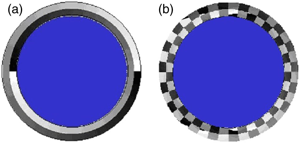
For focusing an azimuthally polarized vortex beam, three polarization components of the electric field are as follows[25]: where is the complex amplitude distribution factor of the incident beam; is the additional phase filter; is a constant; , is the wavelength; and are the azimuthal angle and the half of the converging angle, respectively; is the maximum of . We blocked the circular central part and divided the remaining annular part into an inner annular belt and outer annular belt. When the incident beam is a uniform vortex beam with a topological charge of 1 within the inner annular belt, as is shown in Fig. 1(a). Then, the outer annular belt has a vortex phase distribution of . We azimuthally divided each of two annular belts into fan-shaped areas. , where is an even number. The inner annular belt corresponds to half of the converging angle, in a range from to . When and the incident beam is the azimuthally polarized uniform beam, we let When , Here, is a displacement along the axis. is the additional phase factor, which changes radially at the back aperture[26,27]. Eqs. (1) and (2) show that they both have a phase factor . Obviously, the introduction of additional will cause the displacement of the focal spot along the axis. Because is also closely related to , the uniformity and transverse compression of the final transversely polarized needle-shaped electric field and longitudinal magnetization strongly depend on the half converging angle, and . For intuitive visualization we show the calculated phase distribution of Eqs. (4) and (5) using the parameters: , , , , and . Here, , where is the focal length of the objective. The normalized phase distribution is shown in Fig. 1(b).
Figure 1.(a) Annular vortex filter composed of two annular belts with shift radially between adjacent belts; (b) an azimuthally divided annular vortex filter with additional phase for moving the magnetization needle along the positive and negative direction of the axis.
According to energy considerations[6,8], the magnetization field induced by the IFE can be represented as where is the electric field, is its conjugate, and is a real constant proportional to the susceptibility of the magnetic material. In Cartesian coordinates, when the component of electric field , we have where is the unit vector along the axis. Equations (1), (2), (3), and (7) indicate that focusing the azimuthally polarized beam generates transverse components of the electric field that accordingly induce pure longitudinal magnetization.
To maximize the length of the longitudinal magnetization needle and minimize the transverse size, we use a group of the combination of three different parameters (, , ) to calculate the one-dimensional longitudinal distribution along the axis of the longitudinal magnetization. Figure 2 shows the results. The lines with four different colors denote four different combinations of two semi-angles of convergence, and . Figures 2(a), 2(b), 2(c), and 2(d) correspond to the cases of , , , and , respectively. We see that, when, the red line that is obtained with and has a relatively wide flat top. The FWHM reaches . When , the green line that is obtained with , also has a flat top with a FWHM of . We then calculated the one-dimensional radial distribution of longitudinal magnetization in the cases of both and . The results are given in Fig. 3. It is demonstrated that the FWHM of extremely compressed transverse size is as low as . It should be noted that the values of FWHM describing the transverse size of the longitudinal magnetization needle are all calculated on the focal plane, where we have . At other off-focal-planes the values of the FWHM are usually smaller than that of . The differences of the transverse sizes of the side lobes between Figs. 3(a) and 3(b) or between Figs. 3(c) and 3(d) can attribute to the fact that the super long longitudinal magnetization needle is generated by connecting two properly displaced and relatively short longitudinal magnetization needles. The aspect ratio of the longitudinal magnetization needle is as high as 103 [red line in Fig. 2(b)] and 88 [green line in Fig. 2(c)]. The one-dimensional distribution of the longitudinal magnetization along a transverse line at shows that the main sidelobe accounts for less than 27% of the maximum magnetization value on this transverse line when the parameters are , , and . When the parameters are , , and , this main transverse sidelobe at accounts for less than 24% of the maximum magnetization value on this transverse line. To visualize the aspect ratio and the main sidelobe, we calculated the two-dimensional distribution of the electric field and the longitudinal magnetization in the longitudinal plane of the focal volume, as shown in Fig. 4. Figure 5 shows the three-dimensional half-maximum surface shape of the electric field and the longitudinal magnetization needle.
Figure 2.Longitudinal magnetization distribution along the axis at different , , and . The green line is obtained when , ; blue line is obtained when , ; red line is obtained when , ; and yellow line is obtained when , . (a) ; (b) ; (c) ; (d) .
Figure 3.Normalized longitudinal magnetization distribution along the radial direction at and . The red line is obtained when , and. The green line is obtained when , and . The FWHM in all cases are .
Figure 4.Two-dimensional intensity distribution of (a) the electric field and (b) longitudinal magnetization in the longitudinal plane of the focal volume. The parameters are , , and .
Figure 5.Three-dimensional half-maximum surface of the electric field (left panel) and longitudinal magnetization needle (right panel) in the focal volume.
Compared with the transverse size () of the longitudinal magnetization needle reported in Ref. [23], the transverse size () of the longitudinal magnetization needle created in this method is much smaller. This may attribute to no interference of the light passing through two adjacent fan-shaped areas on the same annular belt at the back aperture of the focusing objective because these two adjacent fan-shaped areas have different additional phase modulation for focusing the light onto two different focal points along the axis. While the light passing through the exactly two opposite fan-shaped areas on the same annular belt will partially cancel out each other or cause destructive interference on the off-axis point in the same transverse plane because the phase difference will not likely be (here, is the even number or zero). As a result, the intensity distribution of the electric field in a transverse plane will mostly concentrate on the on-axis point displaying a smaller transverse size of the longitudinal magnetization needle.
It should be noted here that, based on the difference between the different combination of the half converging angles and for optimizing the needle-shaped longitudinal magnetization and maximizing the aspect ratio, it is revealed that the needle aspect ratio of the longitudinal magnetization is very sensitive to the half converging angles. It means that the phase modulation at the back aperture of the high numerical aperture objective, especially the radial phase distribution, has to be precisely fabricated in the practical application. Fortunately, the state-of-the-art manufacturing equipment is currently available to achieve such precision[28]. Alternatively, we may choose a reflecting pure phase spatial light modulator and a 4F imaging system to perform the precise phase modulation on the incident azimuthally polarized vortex beam[29].
In conclusion, by superimposing an additional phase modulation for moving the needle of the electric field and longitudinal magnetization along the optical axis when an azimuthally polarized vortex beam modulated by an annular phase filter is focused by a high numerical aperture objective, the longitudinal magnetization needle can be elongated to as long as and the transverse size of the needle can be compressed to a FWHM of . The aspect ratio can reach 103, which is more than ten times larger than that of the longitudinal magnetization needle fabricated by electron beam lithography. The longitudinal magnetization needles with high aspect ratios have significant roles in high density magnetic data storage, spin wave operation, atomic trapping, and ferromagnetic semiconductor devices.