Abstract
As perovskite solar cells show tremendous potential for widespread applications, we find that adding inorganic thermal-stable cesium ions into results in significantly improves thermal stability. For un-encapsulated perovskite devices, the energy conversion efficiency maintains about 75% of its original value (over 15%) in the device under 80 min of heating at 140°C in a dry atmosphere (). With significantly improved thermal stability achieved by a convenient process, it is expected that this type of mixed-cation perovskites can further facilitate large scale applications.In the past few years, organolead halide perovskites have captured intensive attention due to their remarkable optoelectronic properties[1–4]. With a high absorption coefficient, long diffusion length, and feasible fabrication processes[3,5,6], perovskites have been widely employed in various optoelectronic applications, such as solar cells[7–12], photodetectors[13,14], light-emitting diodes (LEDs)[2,15,16], and lasers[17–20]. Particularly in the field of photovoltaics (PV)[21–23], the past years have witnessed the rapid development of efficiency from 3.8%[24] to 22.1%[25]. However, due to intrinsic ionic characters and low crystallization energy[26], the stability issue of perovskites (the most used form is ) has become one of the major obstacles toward large scale applications. Compared to significant efforts devoted to the efficiency improvement, much less attention has been paid to enhance the stability[26–31].
As inorganic cesium lead halide perovskites (, , Br, I) have demonstrated advantageous thermal stability[32–34], there have been efforts to develop mixed-cation perovskites with high efficiency and good thermal stability at the same time[26,27,29–31]. Several groups have reported on Cs/FA mixtures, with enhanced stability of photo, moisture, and heat compared to the pure one (). They attribute the stability improvement to lattice shrinkage and entropic stabilization. Saliba et al. have fabricated solar cells using triple-cation perovskites (MA/FA/Cs), also revealing improved reproducibility and stability. The investigation of MA/Cs mixtures and their thermal stabilities are rather limited[27]. Here, by partially substituting () ions with cesium () to form a mixed-cation perovskite (), it is found that the mixed-cation perovskite films exhibit improved thermal durability when exposed at a high temperature (150°C) compared to the pristine perovskite () and confirmed by the absorption spectra and X-ray diffraction (XRD) results. In addition, -based solar cells exhibit more steady performance than -based ones under heat stress tests. To be specific, the power conversion efficiency (PCE) degrades to about 75% of its original value in the -based devices after 80 min of heating at 140°C in the dry atmosphere (). By contrast, the PCE degrades quickly to only about 15% in the devices under the same condition.
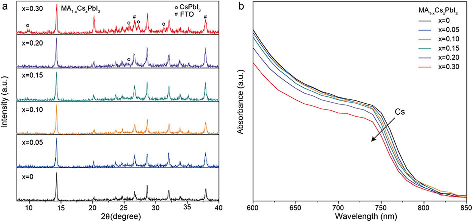
In this work, we investigated mixed-cation perovskites with the general formula and systematically adjusted from 0 to 0.30 ( represents the molar ratio of cesium added initially) to examine their PV performances and thermal stabilities. In Fig. 1(a), we show the XRD data of perovskites with different cesium contents. With a small cesium concentration (), only peaks are observed, and no new phase corresponding to cesium compounds is detected. This demonstrates the complete integration of into the perovskite lattice. When the cesium concentration increases to 20% and 30% ( and ), additional XRD peaks matching with the yellow-phase start to emerge. The appearance of these peaks is a sign of phase separation of and , which can be attributed to the size mismatch between and at relatively high Cs concentrations[26,35]. To carefully examine whether cesium is indeed embedded into the perovskite lattice, the absorption data of films is shown in Fig. 1(b). It is found that with the increased Cs value (), the absorption edge shifts to a blue region, corresponding to increased bandgaps originating from the smaller radius of [27]. Although yellow-phase appears when , the bandgap still shifts to a larger one with the increased Cs content, indicating the continuous substitution of at the larger value.
Sign up for Chinese Optics Letters TOC. Get the latest issue of Chinese Optics Letters delivered right to you!Sign up now

Figure 1.(Color online) (a) XRD patterns of films (). (b) Absorption spectra of films ().
To evaluate the influence of substitution on device performances, we fabricated -based solar cells using conventional mesoporous structures. First, we examined the morphologies of perovskite films with and without Cs doping. Figures 2(a)–2(e) show the scanning electron microscope (SEM) images of () films spin-coated on the mesoporous (mp-) layer. It is clear that for Cs content below 0.20, perovskite films have similar morphologies on grain size and surface roughness. However, when increases to 0.20, rod-like impurities attributed to be yellow-phase confirmed by XRD (Fig. 1) begin to appear on the film surface. The impurity issue becomes more serious when is further increased to 0.30, as shown in Fig. 2(f). Therefore, based on both morphologies by SEM images and crystal quality by XRD data, it is confirmed that with has a full substitution of by without phase separation. Figure 2(g) shows a cross-sectional SEM image of an -based solar cell. From bottom to top, the device consists of several layers of fluorine-doped tin oxide (FTO), blocking (bl-), mp-, perovskite, spiro-MeOTAD, and Au contact. Flat perovskite film was spin-coated on a 250-nm-thick mp-, forming a 390-nm-thick capping layer.
Figure 2.(a)–(e) Top-view SEM images of films for , 0.05, 0.10, 0.15, 0.20, and 0.30. Scale bars are all 250 nm. (g) Cross-section SEM images of a solar cell. The scale bar is 1 μm.
The distinguished differences between the Cs-doped and undoped perovskite solar cells are the open-circuit voltage (). It is clear that by adding cesium to the perovskite matrix, an obvious increase in can be observed, which can be attributed to a change in the quasi-Fermi energy at the perovskite/anode interface due to Cs doping[27]. In Fig. 3(a), we compare two champion cells based on and . A -based device demonstrates a PCE of 10.90% with a of 1.01 V, a short-circuit photocurrent density () of , and a fill factor (FF) of 56.8%. By contrast, with the addition of 15% cesium, the optimized cell with a PCE of 15.03% gives a of 1.05 V, a of , and an FF of 68.5%. The external quantum efficiency (EQE) spectra of devices incorporating and are shown in Fig. 3(b). The integrated current densities from the EQE curve are 19.57 and 18.56 mA/cm2, respectively. The cut-off of shows a small blue shift, corresponding to the absorption spectrum in Fig. 1(b). The PCE distributions of about 15 devices are shown in Figs. 3(c) and 3(d), respectively, revealing an obvious increase of PCE in -based devices compared to that in -based ones. It is also found that when is further increased to 0.20 and 0.30, the device performances deteriorate due to the rod-like impurities forming on top of the films, shown in Figs. 2(e) and 2(f), as these impurities presenting on the top presumably impede the contact between perovskite and hole transporting material (spiro-MeOTAD)[26].
Figure 3.(Color online) (a) Best performances of PV devices incorporating and , respectively. (b) EQE spectra of and -based devices. (c) and (d) PCE distributions of and -based devices.
As has the best PV performance among Cs-doped devices, it is chosen for the systematical study of thermal stability in comparison with . As pure is thermally unstable and can decompose very quickly at 150°C, the amount of product after decomposition (such as ) can serve as the indication of thermal stability. In Figs. 4(a) and 4(b), we compared the peak intensity of and films after being heated at 150°C for 20 min in a glovebox. It is obvious that the intensity of peak at 12.65° [assigned to (001) peak] in Fig. 4(b) is much stronger than that in Fig. 4(a), even though their initial films have similar morphologies and crystallinities. To further heat the films for 3 h at 150°C in a glovebox, it is obvious that the film demonstrated significantly enhanced stability with a much slower fade speed over time. Insets in Figs. 4(c) and 4(d) present the two perovskite films coated on glass substrates before and after 3 h of heating. There are nearly no discriminations on the starting colors of these two. After the same thermal treatment, the film still maintains its initial black color, while turns fully yellowish, indicating the completed deterioration of the initial film.
Figure 4.(Color online) XRD patterns and absorption spectra of and films before and after thermal treatment. (a) and (b) XRD patterns of and films before and after being heated at 150°C for 20 min, respectively. (c) and (d) Absorption spectra of and films before and after being heated at 150°C for 3 h, respectively. For comparison, the insets in (c) and (d) are the photographs of and films before (the left) and after (the right) being heated at 150°C for 3 h.
It is believed that the thermal stability enhancement in results not only from the intrinsic properties of thermal-stable inorganic cesium, but also from the lattice shrinkage and stronger Pb-I interaction due to the incorporation of with a smaller radius[26]. To quantitatively characterize the effect of thermal treatment (for 3 h) on film quality, the absorbance spectra of and films before and after thermal treatment are demonstrated in Figs. 4(c) and 4(d). While these two perovskite films show similar absorption spectra, they initially exhibit high absorption in the wide range of 450 to 750 nm. After being heated at 150°C for 3 h, the absorption of film drops dramatically coupled with an appearance of an additional absorption threshold shoulder located at around 520 nm. This is also confirmed by the film color change from black to yellowish in the inset. By contrast, under the same thermal test, the absorption of shows only slight change in the range from 600 to 750 nm. The less obvious absorption decrease of reveals that although some degradation exists, it is much less pronounced than that of . A concomitant increase in the absorbance () results from Mie scattering within the film[36]. The absorption results further confirm that the addition of 15% cesium can form a thermal-stable mixed-cation perovskite .
Finally, thermal durability of is examined by measuring the device performance over time at an elevated temperature (140°C) in a dry atmosphere (relative humidity ). As shown in Figs. 5(a)–5(d), under the heat stress test at 140°C, all four parameters, , , FF, and PCE, of PV devices embedding show less decay than that of devices with . In the case of , there is no obvious decay of observed, and the decays of both and FF are less than 15%. Consequently, the final PCE remains about 75% of its initial value after the test. For comparison, in the case of , both and FF decay over 20%, and decreases more dramatically (over 75%). Thus, the final PCE of an -based solar cell degrades to only about 15% of its original value because of the thermal decomposition of perovskite. As observed in the insets in Fig. 5(a), perovskite (the left) shows plenty of obvious yellowish vacancies, which can be assigned to . As clearly seen in the insets (right) in Fig. 5(a), the thermal decomposition phenomenon is much less obvious for , which is consistent with device performance under thermal treatment.
Figure 5.(Color online) Thermal stability of devices under a heat stress test at 140°C. (a) Normalized , (b) normalized , (c) normalized FF, and (d) normalized PCE. Insets in (a) are the photographs of devices with (right) and (left) after being heated at 140°C for 80 min.
In this work, we develop a mixed-cation perovskite () by partially substituting the susceptible with a more thermally robust inorganic cesium ion. PV devices based on film maintains steady performances when exposed to 140°C for 80 min with the PCE value maintaining about 75% of its initial value () in perovskite, while the PCE value decreases to only 15% of its initial value () in perovskite devices. After cesium doping, the perovskite also shows a slower decomposition rate during heat treatment at elevated temperatures (150°C), revealing the enhanced structural thermal stability due to a shrink of lattice and stronger Pb-I interaction. It is expected that this kind of perovskite cells with significantly improved thermal stability can further facilitate the commercial feasibility of optoelectronic applications of perovskites.
Materials and Purifications. The perovskite solution was prepared by dissolving 1 mmol of (461 mg), methylammonium iodide (MAI, 159 mg), and dimethyl sulfoxide (DMSO, 78 mg) in 600 mg of dimethylformamide (DMF). For , a corresponding amount of CsI was added (13, 26, 39, 52, and 78 mg of CsI for , 0.10, 0.15, 0.20, and 0.30) instead of MAI.
Device Fabrication. FTO glasses were cleaned in acetone, ethanol, and deionized water in an ultrasonic bath for 30 min, respectively. A 50 nm bl- was deposited on the cleaned FTO by spray pyrolysis and performed at 500°C from a precursor solution of titanium diisopropoxide dis(acetylacetonate) in isopropyl alcohol (IPA, volume ratio ). An mp- layer was deposited on the bl- by spin-coating the colloidal solution containing 1 g of paste (25 nm sized nanoparticles) diluted in 5 g of anhydrous ethanol solution at 4000 rpm for 30 s. The as-prepared perovskite solution was spin-coated on the mp- layer at 4000 rpm for 30 s, and 0.5 mL of diethyl ether was dripped on the rotating substrate after 5 s. Then, the perovskite film was annealed at 100° for 5 min. The 50 μL of spiro-MeOTAD, consisting of 72.3 mg spiro-MeOTAD, 28.8 μL of 4-tert-butyl pyridine, and 17.5 μL of lithium bis(trifl uoromethanesulfonyl)imide (Li-TFSI) solution (520 mg Li-TSFI in 1 mL of acetonitrile) in 1 mL of chlorobenzene, was spin-coated on the perovskite layer at 4000 rpm for 30 s. For the counter electrode, Au was thermally evaporated at an evaporation rate of 0.02 nm/s, reaching a thickness of 80 nm. The device area is defined as by a shadow mask.
References
[1] W. S. Yang, J. H. Noh, N. J. Jeon, Y. C. Kim, S. Ryu, J. Seo, S. I. Seok. Science, 348, 1234(2015).
[2] S. D. Stranks, H. J. Snaith. Nat. Nanotech., 10, 391(2015).
[3] M. A. Green, A. Ho-Baillie, H. J. Snaith. Nat. Photon., 8, 506(2014).
[4] M. M. Lee, J. Teuscher, T. Miyasaka, T. N. Murakami, H. J. Snaith. Science, 338, 643(2012).
[5] Q. Dong, Y. Fang, Y. Shao, P. Mulligan, J. Qiu, L. Cao, J. Huang. Science, 347, 967(2015).
[6] S. D. Stranks, G. E. Eperon, G. Grancini, C. Menelaou, M. J. Alcocer, T. Leijtens, L. M. Herz, A. Petrozza, H. J. Snaith. Science, 342, 341(2013).
[7] H.-S. Kim, C.-R. Lee, J.-H. Im, K.-B. Lee, T. Moehl, A. Marchioro, S.-J. Moon, R. Humphry-Baker, J.-H. Yum, J. E. Moser. Sci. Rep., 2, 591(2012).
[8] N. Ahn, D.-Y. Son, I.-H. Jang, S. M. Kang, M. Choi, N.-G. Park. J. Am. Chem. Soc., 137, 8696(2015).
[9] D. Liu, T. L. Kelly. Nat. Photon., 8, 133(2014).
[10] N. J. Jeon, J. H. Noh, Y. C. Kim, W. S. Yang, S. Ryu, S. I. Seok. Nat. Mater., 13, 897(2014).
[11] H. Zhou, Q. Chen, G. Li, S. Luo, T.-B. Song, H.-S. Duan, Z. Hong, J. You, Y. Liu, Y. Yang. Science, 345, 542(2014).
[12] M. Liu, M. B. Johnston, H. J. Snaith. Nature, 501, 395(2013).
[13] L. Dou, Y. Yang, J. You, Z. Hong, W. H. Chang, G. Li, Y. Yang. Nat. Commun., 5, 5404(2014).
[14] P. Zhu, S. Gu, X. Shen, N. Xu, Y. Tan, S. Zhuang, Y. Deng, Z. Lu, Z. Wang, J. Zhu. Nano Lett., 16, 871(2016).
[15] R. Yan, D. Gargas, P. Yang. Nat. Photon., 3, 569(2009).
[16] Z.-K. Tan, R. S. Moghaddam, M. L. Lai, P. Docampo, R. Higler, F. Deschler, M. Price, A. Sadhanala, L. M. Pazos, D. Credgington. Nat. Nanotech., 9, 687(2014).
[17] M. H. Huang, S. Mao, H. Feick, H. Yan, Y. Wu, H. Kind, E. Weber, R. Russo, P. Yang. Science, 292, 1897(2001).
[18] G. Xing, N. Mathews, S. S. Lim, N. Yantara, X. Liu, D. Sabba, M. Grätzel, S. Mhaisalkar, T. C. Sum. Nat. Mater., 13, 476(2014).
[19] H. Zhu, Y. Fu, F. Meng, X. Wu, Z. Gong, Q. Ding, M. V. Gustafsson, M. T. Trinh, S. Jin, X. Zhu. Nat. Mater., 14, 636(2015).
[20] J. Xing, X. F. Liu, Q. Zhang, S. T. Ha, Y. W. Yuan, C. Shen, T. C. Sum, Q. Xiong. Nano Lett., 15, 4571(2015).
[21] Y. Shi, Z. Li, B. Feng, P. Yan, B. Du, H. Zhou, H. Pan, G. Wu. Chin. Opt. Lett., 14, 030401(2016).
[22] J. Zhang, Y. Chen, Y. Zhu, F. Luo. Chin. Opt. Lett., 12, 073501(2014).
[23] Q. Wu, L. Gu, Z. Tan, C. Wang, J. Cao. Chin. Opt. Lett., 12, 120401(2014).
[24] A. Kojima, K. Teshima, Y. Shirai, T. Miyasaka. J. Am. Chem. Soc., 131, 6050(2009).
[25]
[26] J. W. Lee, D. H. Kim, H. S. Kim, S. W. Seo, S. M. Cho, N. G. Park. Adv. Energy Mater., 5, 1501310(2015).
[27] H. Choi, J. Jeong, H.-B. Kim, S. Kim, B. Walker, G.-H. Kim, J. Y. Kim. Nano Energy, 7, 80(2014).
[28] X. Li, M. I. Dar, C. Yi, J. Luo, M. Tschumi, S. M. Zakeeruddin, M. K. Nazeeruddin, H. Han, M. Grätzel. Nat. Chem., 7, 703(2015).
[29] D. P. McMeekin, G. Sadoughi, W. Rehman, G. E. Eperon, M. Saliba, M. T. Hörantner, A. Haghighirad, N. Sakai, L. Korte, B. Rech. Science, 351, 151(2016).
[30] M. Saliba, T. Matsui, J.-Y. Seo, K. Domanski, J.-P. Correa-Baena, M. K. Nazeeruddin, S. M. Zakeeruddin, W. Tress, A. Abate, A. Hagfeldt. Energy Environ. Sci., 9, 1989(2016).
[31] C. Yi, J. Luo, S. Meloni, A. Boziki, N. Ashari-Astani, C. Grätzel, S. M. Zakeeruddin, U. Röthlisberger, M. Grätzel. Energy Environ. Sci., 9, 656(2016).
[32] G. E. Eperon, G. M. Paternò, R. J. Sutton, A. Zampetti, A. A. Haghighirad, F. Cacialli, H. J. Snaith. J. Mater. Chem. A, 3, 19688(2015).
[33] R. E. Beal, D. J. Slotcavage, T. Leijtens, A. R. Bowring, R. A. Belisle, W. H. Nguyen, G. F. Burkhard, E. T. Hoke, M. D. McGehee. J Phys. Chem. Lett., 7, 746(2016).
[34] R. J. Sutton, G. E. Eperon, L. Miranda, E. S. Parrott, B. A. Kamino, J. B. Patel, M. T. Hörantner, M. B. Johnston, A. A. Haghighirad, D. T. Moore. Adv. Energy Mater., 6, 1502458(2016).
[35] Z. Li, M. Yang, J.-S. Park, S.-H. Wei, J. J. Berry, K. Zhu. Chem. Mater., 28, 284(2015).
[36] J. Yang, B. D. Siempelkamp, D. Liu, T. L. Kelly. ACS Nano, 9, 1955(2015).