
A. F. A. Bott, L. Chen, P. Tzeferacos, C. A. J. Palmer, A. R. Bell, R. Bingham, A. Birkel, D. H. Froula, J. Katz, M. W. Kunz, C.-K. Li, H-S. Park, R. Petrasso, J. S. Ross, B. Reville, D. Ryu, F. H. Séguin, T. G. White, A. A. Schekochihin, D. Q. Lamb, G. Gregori. Insensitivity of a turbulent laser-plasma dynamo to initial conditions[J]. Matter and Radiation at Extremes, 2022, 7(4): 046901
- Matter and Radiation at Extremes
- Vol. 7, Issue 4, 046901 (2022)
Abstract
I. INTRODUCTION
Determining the origin of the dynamically significant magnetic fields in the ionized gases that inhabit the space between clustered galaxies—the so-called intracluster medium—has occupied astrophysicists for over half a century.1,2 One of the most plausible mechanisms that can account for the strength of such magnetic fields is the small-scale turbulent dynamo, whereby the turbulent bulk motion of a conducting fluid or plasma efficiently amplifies the magnetic fields until they have energies that are a non-negligible fraction of the kinetic energy of the driving turbulent motions.3,4 A significant number of analytic calculations5–8 and simulations within the framework of resistive magnetohydrodynamics (MHD)9–19 support the efficacy of this mechanism, provided the magnetic Reynolds number Rm of the plasma exceeds some critical value: Rmc ≈ 50–400.20 The magnetic Reynolds number is defined as Rm ≡ urmsL/η, where urms is the root-mean-square (rms) magnitude of the turbulent motion, L is the characteristic scale of this motion, and η the plasma resistivity.
Of particular importance is the expectation that the characteristic strength of the magnetic field post-amplification primarily depends on the turbulent kinetic energy, provided Rm is supercritical (viz., Rm > Rmc).15,19 This expectation arises because the induction equation that is thought to describe the evolution of the magnetic field is linear in the magnetic field itself, and so the saturation of the dynamo-amplified fields must involve the back-reaction of the Lorentz force on the turbulent flow dynamics. Previous studies have shown that this back-reaction facilitates saturation via a combination of a weakened stretching of the magnetic field lines and relative enhancement of the magnetic diffusion compared to the stretching.13,21,22 This saturation mechanism sets the precise strengths at which magnetic fields are maintained, a quantity of great significance in astrophysical contexts.23–25 It also allows amplification of the initial magnetic energy over many orders of magnitude if it is much smaller than the turbulent kinetic energy. In many astrophysical environments, this property is crucial for resolving the vast discrepancy between the characteristic magnitudes of the observed dynamic fields and the seed magnetic fields generated by processes that can produce magnetic fields in unmagnetized plasmas (such as the Biermann battery1,26).
In contrast, prior research suggests that dynamo-amplified magnetic fields are insensitive to both the strength of the initial seed magnetic fields and specific particularities of the turbulent motions before amplification. For example, analytic studies of the “Kazantsev” dynamo (which has a delta-correlated-in-time velocity field) have shown that, during the kinematic phase of this model, any smooth initial spectrum for the seed magnetic fields tends toward a characteristic Kazantsev spectrum that does not depend on the initial conditions.5,8 This result also holds in some generalized analytic models with finite correlation times.27 In addition, a recent numerical study28 found that, for a Rm-supercritical turbulent flow in a periodic box, information about the strength and statistics of the initial seed magnetic fields was not retained in the saturated state of the associated small-scale turbulent dynamo.
In the last two decades, it has become possible to explore dynamo processes in controlled laboratory experiments. Historically, the first such experiments involved liquid-metal flows, which yielded many significant results: the first kinematic dynamo flow,29 dynamo saturation,30 and dynamo action in a partially stochastic flow.31 However, liquid-metal experiments are limited to certain parameter regimes: incompressible flows whose magnetic Prandtl number Pm is much smaller than unity. The magnetic Prandtl number is defined as Pm ≡ ν/η, where ν is the fluid viscosity. Since Pm is an important parameter for turbulent dynamos15 and is large in many astrophysical environments,13 alternative experimental approaches are needed. A series of recent laser-plasma experiments in which turbulent plasmas are created using grids have started to satisfy this need, producing a series of notable results: first, the demonstration of the amplification of seed magnetic fields generated by a Biermann battery,32–35 and then the operation of a bona fide small-scale turbulent dynamo in a plasma with Rm ≈ 600.36,37 In the last year, another laser-plasma experiment provided time-resolved measurements of the action of a small-scale turbulent dynamo with Rm ≈ 450, and it also accessed the Pm ≈ 1 regime for the first time in the laboratory.38 This advance was possible thanks to design improvements to the platform:39 specifically, changes in the material composition of the plasma and a new, optimized grid design. The amplification of magnetic fields (but not yet a dynamo) has also been observed in a supersonic turbulent laser-plasma,40 an experiment that was based on the first successful realization of boundary-free supersonic turbulence in the laboratory.41 Most recently, a turbulent laser-plasma with Rm ≈ 3500 and Pm ≈ 10 was successfully produced at the National Ignition Facility, with dynamo-amplified magnetic fields of megagauss strengths being observed.42
One finding of previous turbulent-dynamo experiments that merited further study was that the ratio of the magnetic to turbulent kinetic energy density was observed to be finite but still quite small (ɛB/ɛK,turb ≈ 3%–4%).37,38 This prompted the question of whether the characteristic post-amplification strength of the magnetic fields in these turbulent laser-plasmas is determined by only the turbulent kinetic energy of the plasma or was, in fact, not dynamical and, thus, might be expected to be larger in a stronger initial magnetic field. In this paper, we discuss results from a new experiment (in the Pm ∼ 1 regime) at the Omega Laser Facility43 that confirms the former claim. This demonstration is made by introducing a seed magnetic field into a turbulent laser-plasma with Rm > Rmc whose energy is over an order of magnitude larger than the energy of the seed field arising inherently in the plasma. The stochastic magnetic fields that arise from the action of the small-scale turbulent dynamo on the seed field are then compared with a control case (viz., a plasma without an enhanced seed field). The key result is that the characteristic strengths and structure of the magnetic fields are indistinguishable with or without the enhanced seed field and its modest effect on the initial flow dynamics of the plasma.
II. EXPERIMENTAL DESIGN
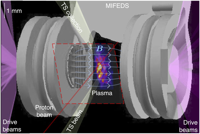
Figure 1 is a schematic of the experimental platform. The target platform was designed based on previous experiments at the Omega Laser Facility:37,38,44 a turbulent plasma is created by colliding rear-side blow-off plasma jets that, prior to collision, have passed through asymmetric grids. On collision, an “interaction region” of plasma forms, which has higher characteristic densities and ion/electron temperatures than either jet. In addition, the asymmetric heterogeneity of the jets leads to the formation of strong shear flows in the interaction-region plasma. These become Kelvin–Helmholtz unstable and turbulent motion quickly develops.
![]()
Figure 1.Schematic of the experimental setup. Twenty beams of the OMEGA laser deliver a total of 10 kJ of 351 nm-wavelength laser-light energy over 10 ns to an 800
The experimental platform outlined here differs from previous experiments in one key regard: the whole target assembly is embedded inside a pulsed magnetic-field generator known as the magneto-inertial fusion electrical discharge system (MIFEDS).45,46 When utilized, the MIFEDS generates a magnetic field with a magnitude of ∼150 kG at the target foil and ∼80 kG at the target center, which is oriented approximately parallel to the axis that passes through the geometric centers of the foils and grids (“the line of centers”). Both plasma jets propagate along this magnetic field. Figure 1 shows a schematic of the magnetic field lines generated by the MIFEDS between the two grids. The magnitude of this magnetic field is significantly larger than that of the magnetic fields (∼10 kG) generated by the Biermann battery and advected to the target's midpoint by the jets.38 However, the effect of a magnetic field of this strength on the dynamics of the interaction-region plasma is modest (as we explicitly demonstrate in Secs. III A and III B). Thus, this platform allowed us to test whether introducing a much larger seed magnetic field into the interaction-region plasma changes the magnitude of the magnetic fields amplified by the turbulent motions.
We characterized the turbulent plasma in both the presence and absence of the MIFEDS (which we refer to as the “MIFEDS experiments” and the “no-MIFEDS experiments,” respectively) using three laser-plasma diagnostics: self-emission x-ray imaging to diagnose the dynamic evolution and turbulence of the plasma, a time-resolved Thomson-scattering diagnostic to assess the physical state of the plasma, and proton radiography using a D3He backlighter capsule to characterize the magnetic fields. The setup used for all these diagnostics was similar to that used in previous turbulent-dynamo experiments at the Omega Laser Facility.37,38 Our methodology for analyzing the data that were collected was also similar. However, for clarity and completeness, we provide a self-contained exposition here for each diagnostic, which both reviews our approach and notes the aspects that are unique to this experiment.
III. RESULTS
A. Characterizing turbulence: X-ray self-emission imaging
The x-ray imaging diagnostic measured soft x rays (∼0.2–0.5 keV) emitted by free–free bremsstrahlung in the fully ionized CH plasma using a pinhole x-ray framing camera (XRFC) configured with a two-strip microchannel plate (MCP) and charged-coupled device (CCD) camera at different times.47,48 The technical specifications of this XRFC were identical to those of the previous experiments;38 the magnification of the imaging was 2×, the pinhole diameter was 50 µm, a thin filter (0.5 μm-thick polypropylene with a 150 nm-thick aluminum coating) was positioned in front of the MCP to block low-energy electromagnetic radiation (≲0.1 keV), and each strip of the MCP was operated at two independent times, each with a 1 ns gate. The only difference with previous x-ray imaging diagnostic setups was the orientation of the camera. In this experiment, the XRFC was oriented at ∼30° with respect to the plane of the interaction-region plasma (60° with respect to the line of centers), to observe fluctuations in the emissions by the plasma within that plane. Previously, x-ray imaging was carried out in a side-on configuration (viz., at 90° with respect to the line of centers). However, due to the narrow extent of the interaction region with respect to the line of centers, detecting turbulent fluctuations during the ∼5 ns interval subsequent to collision proved to be challenging with this configuration. Figure 2 shows XRFC images from the experiment both before and after the jet collision.
![]()
Figure 2.XRFC images of soft x rays emitted by the turbulent plasma in both the presence (left) and absence (right) of the MIFEDS. The top row (22.5 ns after the start of the drive-beam) employed a 100 V bias on the XRFC, whereas all other (post-collision) images used 350 V (the former having 32× sensitivity). The resolution of the images, which is set by the pinhole size and the MCP response, was ∼50
Before the collision in both the MIFEDS and no-MIFEDS experiments (top row of Fig. 2), we observe finger-like regions of emission from the plasma jets. Once these jets have collided (second and subsequent rows of Fig. 2), a region of strong, fluctuating emission develops, which originates from the interaction-region plasma. The fluctuations are related to density inhomogeneities in the plasma, whose origin can, in turn, be attributed to the effect of turbulent motion. Using a technique that was previously applied to similar x-ray imaging data,38 we can extract “maps” of relative-intensity fluctuations for each of these post-collision images by first constructing a smooth mean x-ray intensity profile (as described below) and then dividing the total intensity by this profile. The resulting relative-intensity maps are shown in Fig. 3.
![]()
Figure 3.Maps of fluctuations in the detected x-ray intensity relative to a smooth mean intensity profile. The gray shaded regions denote the intervals over which the mean x-ray intensity profile is averaged when determining
The mean profiles are determined from the raw data using a two-dimensional (2D) mean filter of size 81 × 81 pixels. Given the effective 9 μm-pixel size of the images, this corresponds to a characteristic smoothing scale of ∼0.8 mm (a value chosen to be intermediate between the transverse extent li of the interaction-region plasma and the grid periodicity L). This is then combined with a Gaussian-smoothed indicator function for the interaction-region plasma. The indicator function has a characteristic smoothing scale of 150 µm, which is equal to the characteristic length scale of the raw x-ray intensity profile in the direction parallel to the line of centers. The indicator function is utilized to account for the sharp drop in the measured x-ray intensity associated with the accretion shocks that circumscribe the interaction-region plasma.
Comparing the x-ray images obtained in the MIFEDS and no-MIFEDS experiments, we found that the emission from the incident plasma jets was slightly more extended and collimated in the former case (a physical explanation for this effect is provided with the help of Thomson scattering data in Sec. III B). However, once the interaction-region plasma has formed, the emission is qualitatively similar, irrespective of whether the MIFEDS is turned on or not. This applies to both the size of the region from which x rays are emitted and the fluctuations in x-ray intensity.
To confirm these conclusions more robustly, we performed a quantitative analysis of the x-ray images. First, we measured the transverse extent li of the interaction-region plasma in both MIFEDS and no-MIFEDS experiments by averaging the same mean x-ray intensity profiles that we mentioned previously in the direction parallel to the line of centers. Then, we calculated the full width at half maximum (FWHM) of the resulting one-dimensional profile. The results, which are presented in Fig. 4(a), show that the li values from both types of experiment are, indeed, indistinguishable within the error of the measurement. The uncertainty of the measurement was estimated by assuming that the interaction-region plasma is approximately homogeneous and then considering the left-hand and right-hand sides of the interaction region as independent samples (cf. Fig. 3, top left panel).
![]()
Figure 4.Quantitative analysis of x-ray images. (a) Evolution of the transverse width of the interaction region
To show quantitatively that the statistical properties of the turbulence are not significantly affected by the presence of the MIFEDS, we make use of the interaction-region plasma being optically thin to its bremsstrahlung-dominated x-ray emission38 to relate the relative intensity fluctuations to path-integrated relative density fluctuations.49 Then, under the assumption of approximately isotropic and homogeneous density statistics (which are justified by a previous analysis of similar experiments38), we can determine the rms of the relative density fluctuations and their integral scale ln. These quantities are shown in Figs. 4(b) and 4(c), respectively. The uncertainty of the measurement in Figs. 4(b) and 4(c) was estimated in a similar manner to that described for Fig. 4(a), but using the upper and lower regions of the interaction-region plasma instead of the left- and right-hand sides. Note that our estimates of the rms of the relative density fluctuations and ln are not sensitive to the mean-filter length scale used to construct the mean x-ray intensity profile, provided it is chosen to be inside the interval [L, li].
The results are again similar for the MIFEDS and no-MIFEDS experiments, with one exception: the rms of the relative density fluctuations not long after the collision is larger in the presence of the MIFEDS magnetic field. We attribute this difference to a slightly earlier collision time in the MIFEDS experiments (Sec. III B), which leads to an earlier onset of the turbulent motion. The characteristic value (∼0.5) of the rms of the relative density fluctuations in both the MIFEDS and no-MIFEDS experiments is close to values derived in previous experiments, as is the value of the integral scale ln, which is comparable to the grid periodicity L.38
Under the same assumptions of statistical homogeneity and isotropy, we can also determine the spectrum of the turbulent density fluctuations in the plasma from the spectrum of the intensity fluctuations. Since the turbulent motion is subsonic, the density does not vary much and behaves as a passive scalar. Thus, its spectrum is simply that of the turbulent velocity field.50 This property, which implies that the integral scale lV of the turbulent velocity is approximately equal to that of the density (lV ≈ ln), was observed directly in a MHD FLASH simulation of similar (no-MIFEDS) experiments.38 The inferred turbulent spectra in these experiments are shown in Fig. 5; we evaluated the (wavenumber-dependent) uncertainty of the measurement by combining the ∼10% uncertainty associated with the signal-to-noise ratio of the x-ray images with the standard error in the inferred spectrum that arises when the upper and lower regions of the interaction-region plasma are treated as independent samples. The inferred turbulent spectra have a similar shape, irrespective of both the time of the measurement and whether the MIFEDS magnetic field was present or not. The spectral peak is at a wavenumber ∼2π/L ≈ 20 mm−1, with spectra consistent with a Kolmogorov −5/3 power law at larger wavenumbers.
![]()
Figure 5.Inferred spectra of relative x-ray density and velocity fluctuations in the plasma at four different times in the presence and absence of the MIFEDS magnetic field.
In summary, we conclude that while there are some modest differences in the initial dynamical evolution of the plasma when the MIFEDS is present, the key properties of the plasma turbulence in the interaction region are essentially unaffected by it.
B. Diagnosing the physical state of the plasma: Thomson scattering
For the Thomson-scattering diagnostic employed in the experiment, a 30 J green laser probe beam (with wavelength 526.5 nm) was focused onto the center of the target (and hence, the center of the interaction-region plasma). The scattered light was collected at an angle of 63°. The orientation of the beam is shown in Fig. 1. In this experiment, rather than carrying out measurements that were time-integrated over a 1 ns interval but spatially resolved along a 1.5 mm × 50 µm2 cylindrical volume, as was done previously,38 we instead performed time-resolved measurements in a 50 µm3 volume over the 1 ns interval. To obtain time-resolved measurements over the complete evolution of the interaction-region plasma, we repeated the experiment but applied the Thomson-scattering probe beam at different times.
For a selection of different times around (and after) the formation of the interaction-region plasma, the “high-frequency” electron-plasma-wave (EPW) feature was successfully measured on a spectrometer. The data shown in Fig. 6(a) were successfully collected for one shot without MIFEDS and three shots with MIFEDS. For reasons that remain uncertain, we were unable to detect successfully the "low-frequency" ion-acoustic-wave (IAW) feature, since an anomalous signal saturated the spectrometer on which we had planned to detect this feature at the wavelengths over which it is typically observed.
![]()
Figure 6.Thomson-scattering data and fitting. (a) Time-resolved EPW spectral features obtained in the experiment. The absolute magnitude of the signals was normalized to the same value in each image. For the no-MIFEDS experiment (far left panel), the spectrometer used to detect the EPW spectral feature gave an erroneous output for a 200 ps interval centered at 24.0 ns; this output is masked. (b) Plot of the experimental signal (solid red line) obtained from the raw data shown in the far-left panel of (a) by averaging over a 100 ps interval centered at 24.15 ns (viz., the interval indicated by the white translucent region). The blue dot-dashed line indicates the fit to the background signal that we subtract prior to constructing a best-fit model to the EPW spectral feature. (c) Plot of the experimental signal (with the background subtracted) obtained from the raw data shown in the mid-left panel of (a) by averaging over an 100 ps interval centered at 24.15 ns, along with three possible spectral fits with different mean electron number densities:
We model the EPW feature using the well-established theory for the Thomson-scattering spectra that arise in plasmas.51 In general, the Thomson-scattered spectrum I(
We then adopt the Salpeter approximation for the form factor.51 This approximation is valid in a plasma with Maxwellian electron and ion distribution functions whose electron and ion temperatures Te and Ti and electron and ion number densities ne and ni = ne/Z, where Z is the ion charge, are such that α ≡ 1/kλD ≫ 1, where λD is the Debye length. This is a reasonable assumption for the experimental conditions. For the Salpeter approximation,
Finally, in a turbulent plasma, the presence of density fluctuations in the interaction-region plasma typically gives rise to a range of electron number densities within the scattering volume. To capture this effect, we assume that ne is isotropic and normally distributed in the scattering volume, with mean value and standard deviation Δne. The EPW feature can then be modeled by
Having established a model for the EPW feature, we fit the data as follows. First, we perform a background subtraction to remove signals from the spectrometer that are unrelated to the EPW feature. The background signal is approximated using (Gaussian-filtered) samples taken just before and after the duration of the Thomson-scattering probe beam. We then interpolate those signals to a given time. A typical background signal determined using this approach is shown in Fig. 6(b).
Then, we fit Eq. (4) for particular choices of , Te, and Δne against samples of data averaged over 100 ps. We substitute for ω in terms of the wavelength λ using the dispersion relation ω = ω(λ) of a light wave passing through a plasma. The approach for choosing , Te, and Δne differs depending on whether we are fitting EPW features close to the collision of the plasma jets or subsequent to it. In the former case, we assume that turbulence has not yet developed and set Δne = 0. We then vary and Te to obtain the best fit for the position and width of the peak. In the latter case, we are faced with degeneracy, as changes to either Δne or Te have very similar effects on the width of the spectral peak. To overcome this degeneracy, we infer an estimate for Δne from the measurements of relative density fluctuations obtained using the x-ray imaging diagnostic (Sec. III A). Namely, we assume that the rms of the electron number density fluctuations on the scale lT of the Thomson-scattering volume is related to the rms of the electron number density fluctuations at the integral scale of the turbulence via a Kolmogorov scaling: . The validity of this assumption was tested in our previous experiments,38 in which explicit measurements of were possible due to successful simultaneous measurements of both the IAW and EPW features. These measurements recovered similar values to those inferred from the x-ray images. We then (once again) adjusted and Te to give the best fit for the position and width of the EPW spectral feature.
Once a best fit is obtained, we assess its sensitivity by first determining how the peak position responds to changes in while keeping Te fixed [Fig. 6(c)]. Next, we vary Te and concurrently in such a way that the peak position remains fixed but its width changes [Fig. 6(d)]. We conclude from this analysis that the combined sensitivity of the fits to changes in ne is ±25%, whereas the sensitivity to changes in Te is ±50% (taking correlated uncertainties into account). Finally, the sensitivity of the fits to our assumptions concerning the magnitude of Δne is illustrated in Fig. 6(e). We found that, in the absence of any turbulent broadening, the inferred electron temperatures would be ∼50% larger.
The mean electron number densities and temperatures Te derived from the fitting procedure for all of the data are shown in Fig. 7. The uncertainties were determined from the sensitivity of the fits: ±25% for ne and ±50% for Te. In the MIFEDS experiment, we were unable to construct a fit for the electron temperature at 24.3 ns due to the distortion of the EPW signal.
![]()
Figure 7.Thomson-scattering derived measurements of the physical state of the plasma showing the evolution of the electron number density and temperature in the presence and absence of the MIFEDS magnetic field around and just after collision, as inferred from spectral fits.
For the time interval 23.5–24.5 ns, during which we have data for both the MIFEDS and no-MIFEDS experiments, we observe significant differences in the physical properties of the plasma. Namely, the inferred values of ne are much larger in the former case, and rapid heating of the electrons is observed in the presence of MIFEDS but not in its absence. A compelling explanation for these observations is that the collision between the opposing plasma jets occurs ∼1 ns earlier (at ∼24 ns) in the MIFEDS experiments than in the no-MIFEDS experiments (in which the collision occurs at ∼25 ns based on prior measurements38). The physical origin of this timing difference can be attributed to the dynamical collimation by the MIFEDS magnetic field of the jets. Using the data in Fig. 7 to quantify the parameters of the jets just before they collide (ρjet ≈ 6 × 10⁻⁵ g/cm3 and Te,jet ≈ Ti,jet ≈ 100 eV), it follows that the characteristic kinetic-energy density of the transverse expansion of the jets is comparable to the magnetic-energy density erg cm−3 of the MIFEDS magnetic field. We estimated that the kinetic-energy density of the transverse expansion was erg cm−3 by assuming that the expansion velocity ujet⊥ is given by the sound speed cs ≈ 1.0 × 107 cm/s in the jet. Therefore, the transverse expansion of the jets is at least partially inhibited by the MIFEDS magnetic field, a conclusion that is supported by the x-ray imaging observations (Fig. 2, top row). It is, in turn, plausible that this collimation is associated with a small increase in the parallel velocity of the jets. The inferred collision timing difference is consistent with an ∼5% increase in the initial jet velocities for the no-MIFEDS experiments to ujet ≈ 2.4 × 107 cm/s. Note that, although the MIFEDS magnetic field does seem to have a dynamical effect on the plasma jets, the total characteristic kinetic-energy density of either jet ( erg) is indeed significantly larger than , as claimed in Sec. II.
In contrast, the Thomson-scattering measurements of the parameters for the interaction-region plasma in the MIFEDS experiments post-collision are similar to those in the no-MIFEDS experiments. A few nanoseconds after the collision, the characteristic temperatures Te ≈ Ti ≈ 250–450 eV and electron number densities –, which are close to those inferred from previous experimental data collected at the Omega Laser Facility.37,38 Although we did not make direct measurements of the rms turbulent velocity in the MIFEDS experiments, the inferred ∼5% difference in the incident jet velocities between the MIFEDS and no-MIFEDS experiments is small enough that, given the much larger ∼40% uncertainty of the turbulent-velocity measurements in previous OMEGA experiments, we believe that it is reasonable to infer that the turbulent velocities in the no-MIFEDS and MIFEDS cases are similar (urms ≈ 110 km/s). Therefore, we conclude that a subsonic, turbulent plasma, with a turbulent Mach number –0.7, a fluid Reynolds number Re ≈ 100–900, and a (reasonably large) magnetic Reynolds number Rm ≈ 200–450, was indeed realized in this experiment,71 with the turbulent dynamics of that plasma being minimally affected by the MIFEDS magnetic field. This latter conclusion is consistent with that derived from the x-ray imaging diagnostic.
C. Diagnosing the magnetic fields of the plasma: Proton radiography
The source of the protons for the proton-radiography diagnostic utilized in the experiment was a spherical aluminum-coated SiO2 capsule (thickness 2 µm and diameter 420 µm), filled with D3He gas at 18 atm, with the center of the capsule a distance rs = 1 cm away from the target's center. This proton source has been carefully characterized in numerous prior studies.53–55 Upon irradiation with ∼8 kJ of laser energy over a 1 ns interval, the capsule implodes in a few hundred picoseconds. DD and D3He nuclear fusion reactions, given by
In contrast to previous Omega experiments investigating turbulent-dynamo processes, the proton radiography in this experiment was performed in a side-on configuration with respect to the interaction-region plasma, to accommodate the change in the orientation of the XRFC diagnostic. To obtain radiography measurements at different times, we repeated the experiments but changed the relative timing of the capsule implosion with respect to the drive beams incident on the CH foils.
In our experiments, proton-radiography data provide a wealth of information about the magnetic fields encountered by the protons as they travel from the source to the detector. In the absence of any such fields, the proton-radiography beam would retain its inherent homogeneity, and thus, the proton flux measured at the detector would be close to uniform. In reality, magnetic fields are encountered, and the action of Lorentz forces associated with these fields causes small deflections in the proton trajectories, changing the location at which they arrive at the detector. In general laser-plasma experiments, electric fields could also cause these deflections. However, for laser-plasma dynamo experiments such as ours, their impact is minimal.37 If the proton beam is partially blocked prior to its interaction with the magnetic fields, the deflection of the beam can be directly visualized, providing a very simple way to assess the path-integrated magnetic field.
If the magnetic fields are also spatially heterogeneous, this can lead to significant transverse inhomogeneities in the proton beam, as seen at the detector. Such inhomogeneities can be analyzed quantitatively using a (now well-established37,38,40,56–59) technique that directly relates proton-flux inhomogeneities to the magnetic field path-integrated along the trajectory of the beam protons using a field-reconstruction algorithm.60,61 The technique is formally valid under a set of assumptions that are satisfied in the proton radiography setup, and it has been cross-validated on the Omega Laser Facility using Faraday rotation measurements.62
The proton-radiography diagnostic was first used to perform a calibration measurement of the MIFEDS-generated magnetic field, confirming that it had the expected strength and orientation. For this measurement, the MIFEDS was activated and the D3He capsule imploded, but the drive beams incident on the target CH foils were not fired. The resulting 15.0 and 3.3 MeV proton radiographs are shown in Fig. 8.
![]()
Figure 8.Calibration measurement of the MIFEDS magnetic field with proton radiography. Left: 15.0 MeV proton radiograph of the target in the absence of any drive beams but with MIFEDS on. The axes of the image, which has a 28× magnification, are rescaled so that lengths are directly comparable with the plasma scale. The reported pixel counts are normalized to their mean value (∼60 protons/pixel) in a 0.1 × 0.1 cm2 square whose midpoint is at the center of each image. Right: 3.3 MeV proton radiograph for the same setup. In both panels, the red line marks the apparent boundary of the 15.0 MeV proton beam, while the gold line marks the apparent boundary of the 3.3 MeV proton beam. The solid purple line marks the boundary of both proton beams in the absence of any magnetic fields. It was inferred from the relative displacement of the apparent boundary of the 15.0 and 3.3 MeV beams. The short-dashed, medium-dashed, and long-dashed lines denote the observed boundary of the 15.0 MeV proton beams at 25.2, 31.2, and 38.7 ns, respectively, in the no-MIFEDS experiments. In these images, the line of centers is vertical and the targets and grids lie at the top and the bottom of it.
For a magnetic field oriented as in Fig. 1 (viz., approximately parallel to the line of centers), it was expected that the protons passing through the center of the target assembly would be displaced toward the left side of the detector, with the 3.3 MeV protons displaced further than the 15.0 MeV protons. This is, indeed, what is observed in Fig. 8. Namely, before passing through the center of the target assembly, a part of each proton beam is blocked by a wire associated with the MIFEDS. The apparent boundary of this wire is further to the left in the 3.3 MeV proton radiograph than in the 15.0 MeV radiograph.
More quantitatively, the path-integrated magnetic field experienced by protons traversing the MIFEDS magnetic field can be explicitly estimated from the relative displacement of the boundary. In a point-projection radiography setup, it can be shown63 that the displacements and ΔxDD of protons from their undeflected position on the detector are given by and ΔxDD ≈ rdΔvDD/vDD, respectively. Here and ΔvDD are the velocity perturbations of the 15.0 and 3.3 MeV protons acquired due to the interaction with the magnetic field, and and vDD are the initial speeds of the 15.0 and 3.3 MeV protons. In the limit of small deflections, is independent of the proton velocity, where B⊥ is the component of the magnetic field perpendicular to the direction of the proton beam, e is the elementary charge, c the speed of light, and mp the proton mass. Thus, it follows that
Having calibrated the MIFEDS magnetic field strength and morphology, we then performed comparative measurements of magnetic fields arising in the turbulent interaction-region plasma with and without the MIFEDS switched on. Figure 9 (left column) shows the radiographs for the 15.0 MeV proton recorded just after the collision. It is clear that the inhomogeneities of the proton flux are more pronounced in the MIFEDS experiments than in the no-MIFEDS ones. Because these inhomogeneities can be attributed to the deflection of the proton beam by Lorentz forces associated with non-uniform magnetic fields present in the plasma,63 this implies that the seed fields are stronger.
![]()
Figure 9.Proton radiography measurements of magnetic fields at collision. Left column: 15.0 MeV-proton radiographs in the presence and absence of the MIFEDS at 25.2 ns (at a time close to the collision of the plasma jets). The pixel counts of each image are normalized to their mean value (∼60 protons/pixel) in a 0.1 × 0.1 cm2 square whose midpoint is at the center of each image. In these images, the line of centers is vertical and the targets and grids lie at the top and bottom of it. The interaction region is offset by ∼0.05 cm leftward in the MIFEDS image due to the effect of the large-scale MIFEDS magnetic field. Right column: Magnitude of the “small-scale” components of the path-integrated magnetic field that is perpendicular to the trajectory of the proton radiography beam. In each case, we determine this quantity over a region that is approximately coincident with the location of the interaction-region plasma, and only show those fluctuations in the path-integrated magnetic field whose characteristic scale is smaller than the characteristic size of the region analyzed. When the MIFEDS is on, we recover a large-scale path-integrated magnetic field in addition to the small-scale path-integrated field that causes the deflection of protons leftward. To enable a direct comparison, this field is not shown, and the positioning of the small-scale path-integrated field in these cases is adjusted to take this deflection into account.
Figure 9 (right column) shows 2D maps of the path-integrated magnetic field reconstructed using a field-reconstruction algorithm.60 When the MIFEDS is on, we estimate that the initial magnetic-field strength in the interaction-region plasma is
In contrast to our findings close to the jet collision, both the (stochastic) proton-flux inhomogeneities and the reconstructed path-integrated magnetic fields are much more similar over one driving-scale turbulent eddy-turnover time (∼6 ns) after collision (Fig. 10), and also over three driving-scale eddy-turnover times (∼13.5 ns) after the collision (Fig. 11). Qualitatively, the proton radiographs from the MIFEDS and no-MIFEDS experiments are not completely identical. A significant proton-flux inhomogeneity with a magnitude much greater than the mean proton flux of the image, which is associated with the interaction of the MIFEDS field with the edge of the interaction-region plasma, is evident for the former on the right of the radiographs. However, the stochastic proton-flux inhomogeneities in the center of the interaction-region plasma are much harder to distinguish, as are the stochastic path-integrated fields.
![]()
Figure 10.Proton radiography measurements of magnetic fields post-collision. Left column: 15.0 MeV proton radiographs in the presence and absence of the MIFEDS ∼6 ns after collision. Each image is normalized to its mean value (∼60 protons/pixel) in a 0.1 × 0.1 cm2 area in the center of each image. In these images, the line of centers is vertical and the targets and grids lie at the top and bottom of it. The interaction region is offset by ∼0.05 cm leftward in the MIFEDS image due to the effect of the large-scale MIFEDS magnetic field. The long horizontal feature in the MIFEDS image lies to the right of the interaction region (see text). Right column: Magnitude of the small-scale components of the (perpendicular) path-integrated magnetic field.
![]()
Figure 11.Proton radiography measurements of magnetic fields at late times. Left column: 15.0 MeV proton radiographs in the presence and absence of the MIFEDS 13.5 ns after collision. The proton flux is detected using a CR-39 detector stack. The pixel counts of each image are normalized to their mean value (∼60 protons/pixel) in a 0.1 × 0.1 cm2 square whose midpoint is at the center of each image. In these images, the line of centers is vertical and the targets and grids lie at the top and bottom of it. The interaction region is offset by ∼0.05 cm leftward in the MIFEDS image due to the effect of the large-scale MIFEDS magnetic field. The long horizontal feature in the MIFEDS image lies to the right of the interaction region (see text). Right column: Magnitude of the small-scale components of the (perpendicular) path-integrated magnetic field.
Assuming that the magnetic field has isotropic and homogeneous statistics, we estimate the rms magnetic-field strength Brms from the path-integrated magnetic-field maps via the relation , where ℓB is the field correlation length.60 For both the MIFEDS and no-MIFEDS experiments ∼6 ns after collision, we obtain
We can also estimate the magnetic-energy spectrum via the relation
![]()
Figure 12.Proton radiography measurements of magnetic-energy spectra. Spectra obtained from no-MIFEDS experiments are shown in red, and those from MIFEDS experiments in blue. The nominal limit on the resolution due to the finite size of the proton source is indicated on each plot. However, the actual resolution scale is observed to be a few times larger than indicated due to a systematic blurring of the proton-radiography data that stems from self-intersection of the proton beam prior to its detection. The self-intersection is caused by small-scale stochastic magnetic fields in the plasma.40,60 The uncertainty of the measurement of the spectra was estimated by assuming that the interaction-region plasma is homogeneous, and then treating the left- and right-hand sides of the interaction region as independent samples. Left: 31.2 ns after collision. Right: 38.7 ns after collision.
The similarity of the magnetic field strengths and morphologies between the MIFEDS and no-MIFEDS experiments is also evident in the proton-radiography data, reconstructed path-integrated magnetic fields, and magnetic-energy spectra obtained at the later times (Fig. 12, right panel). Intriguingly, even though the correlation length is similar, the characteristic value of the rms magnetic-field strength is somewhat reduced at late times compared to earlier ones in both MIFEDS and no-MIFEDS experiments: Brms ≈ 50 kG at 38.7 ns compared with Brms ≈ 100 kG at 31.2 ns. A plausible explanation for this observation is the decay of the turbulent kinetic energy by this stage of the evolution of the interaction-region plasma, which has been seen in simulations of similar experiments.38
In summary, the proton radiography data confirm that the magnetic field in the interaction-region plasma post-amplification is not significantly altered by the MIFEDS, despite the much stronger seed magnetic fields and somewhat distinct initial flow dynamics in the interaction-region plasma.
IV. DISCUSSION
In the experiments described above, we found that using the MIFEDS to introduce a magnetic seed field (B0 ≈ 60 kG) into a turbulent, Rm-supercritical laser-plasma that is six times larger than the inherent seed field self-generated by the Biermann battery does not lead to larger values of Brms post-amplification. Instead, the same value is measured in both MIFEDS and no-MIFEDS experiments (Brms ≈ 100 kG; Sec. III C). Further, the statistics of the amplified magnetic fields arising in both types of experiments could not be distinguished. This result was attained despite the MIFEDS seed field being strong enough to modify (somewhat) the dynamics of the counter-propagating jets that form the turbulent plasma when they collide (Sec. III A).
One immediate corollary of this finding is that the amplified magnetic field in the turbulent plasma must be dynamically significant. In resistive MHD, which is a reasonable model for the collisional CH laser-plasmas in our experiments, the evolution of a dynamically insignificant field is linear and thus, is proportional to B0. We conclude that Brms cannot be dynamically insignificant with respect to turbulent motion in the interaction-region plasma, because if it were so, then introducing the larger seed field using the MIFEDS would have resulted in larger magnetic field strengths post-amplification. This result is, perhaps, surprising, given that the magnetic to turbulent-kinetic energy ratio is only ɛB/ɛK,turb ≈ 3%. However, periodic-box MHD simulations of a small-scale (subsonic) turbulent dynamo with similar Rm and Pm values in which back-reaction can be explicitly identified found that, in fact, the magnetic field begins to back-react on the turbulent motion once ɛB/ɛK,turb ≳ 1%.19
Our result that the strength and structure of dynamically significant dynamo-amplified magnetic fields are not sensitive to the strength of the initial seed fields is generally consistent with the results of periodic-box MHD simulations of a small-scale turbulent dynamo. For example, one recent study of this type28 found that the characteristic values of Brms, the correlation length lB, and the magnetic-energy spectrum EB in the saturated state of a turbulent dynamo with Rm = 2000, Pm = 1, and were indistinguishable for two different seed-field strengths [ɛB/ɛK,turb(t = 0) ≈ 8 × 10⁻¹⁰ and ɛB/ɛK,turb(t = 0) ≈ 8 × 10⁻¹², respectively], and also three qualitatively distinct seed magnetic-energy spectra. That being said, the initial seed-field strengths in these simulations were much smaller than in our experiment, and we are not aware of any periodic-box simulations that are more directly comparable in terms of parameters and that also investigated the role of seed fields on the dynamo.
The ∼3% value of the magnetic-to-kinetic energy ratio that we observed, which is consistent with the maximum values of this quantity seen in earlier comparable laboratory experiments,37,38 merits further discussion. It was previously noted38 that the saturation values of ɛB/ɛK,turb in periodic-box simulations of a subsonic small-scale turbulent dynamo at comparable Rm and Pm tend to be somewhat larger (ɛB/ɛK,turb ≈ 8%13,19) than the reported experimental values. One explanation for this discrepancy is that the field growth became fully saturated in the experiments at a smaller energy ratio because the turbulent flow itself is qualitatively different from that in periodic-box simulations. These differences include the interaction-region plasma in the experiment not being fully incompressible (which is predicted theoretically to alter the saturation value64,65) and also not spatially homogeneous and periodic. In the latter regard, strong shear flows in the interaction-region plasma were identified in addition to turbulent motion38 in MHD simulations of a previous experiment completed using FLASH. Another (previously proposed38) explanation for this discrepancy was that an insufficient number of driving-scale eddy-turnover times had passed in the experiments for the dynamo to have saturated.
In light of the new results reported in this paper, the latter of the two explanations might seem untenable, as it would require identical transient magnetic-field strengths to be reached when starting with two different seed fields over the same period of time. However, this explanation cannot, in fact, be ruled out or corroborated by our new experimental results. This is because the initial field in the MIFEDS experiment (B0 ≈ 60 kG), while larger than in the no-MIFEDS one (B0 ≈ 10 kG), is still small enough for its amplification to start in the kinematic phase of dynamo action. In both experiments, the magnetic field first grows exponentially fast at a rate γkin to a dynamical strength Bnl over a very short time tkin, and then spends most of the time being amplified further in the nonlinear, secular regime. It is then natural that measurements at a time interval Δt ∼ 6 ns ≫ tkin after the jet collision would find the same state. Based on previous time-resolved measurements of the magnetic field,38 we estimate that γkin ≈ 1.8 × 10⁹ s−1 and Bnl ≈ 86 kG, so that tkin ≈ 1.2 ns (Δt − tkin ≈ 4.8 ns) in the no-MIFEDS experiments and tkin ≈ 0.2 ns (Δt − tkin ≈ 5.8 ns) in the MIFEDS ones. In both cases, Δt − tkin is comparable to ∼1–2 driving-scale eddy turnover times τeddy (∼4 ns). Assuming that periodic-box simulations are applicable, then saturation of the dynamo in them takes ∼3–5τeddy after the beginning of the nonlinear dynamo regime, a somewhat longer period than our experiment lasts. We, therefore, remain uncertain about whether the dynamo was fully saturated in these experiments.
This conclusion clearly points toward the most pressing future direction for laser-plasma experiments investigating a small-scale turbulent dynamo: more experiments with time-resolved measurements over a longer period or with larger seed fields and closer to the current level achieved at the end of the experiment. Only then will it possible to confirm definitively whether the dynamo in the experiments has saturated. An experimental program of this sort would have other tangible benefits too. For example, MIFEDS experiments with time-resolved proton-radiography measurements taken at a shorter interval (as has already been done for the no-MIFEDS experiments38) would allow for a more detailed comparison of the key properties of the magnetic field (including some not measurable from our current data, e.g., the growth rate of the field). If such measurements were successfully made just after the formation of the interaction-region plasma, it might also be possible to determine directly the initial spectrum of the seed magnetic fields on which the turbulent dynamo acts directly. Such a measurement would extend our results, if this spectrum differed between MIFEDS and no-MIFEDS experiments.
In summary, our results support a key prediction of theoretical dynamo theory: that, in a turbulent, magnetized fluid, changing the initial seed-field strength (and also modestly changing the initial conditions of the turbulence) does not lead to larger characteristic magnetic-field strengths post-amplification. More generally, it also suggests that in turbulent, Rm-supercritical plasmas, magnetic fields will tend to undergo quasi-spontaneous amplification and become dynamically significant. In addition to the astrophysical applications discussed in the introduction, this conclusion is also relevant to inertial-confinement fusion (ICF) experiments. More specifically, if turbulence-generating fluid instabilities such as the Rayleigh–Taylor instability are also present in ICF implosions and high enough plasma temperatures are attained to realize Rm supercriticality, it is possible that the Biermann-battery fields self-generated during those implosions could be further amplified.66 If these fields become strong enough to magnetize the electron species of the ICF plasma (viz., by bringing the Hall parameter to order unity), the electron thermal conductivity of the plasma would be altered significantly,67,68 which, in turn, would affect key metrics such as ion temperature and neutron yield. Such an effect has been reported in 3D extended-MHD simulations of the stagnation phase of an indirect-drive implosion at the National Ignition Facility.69 If magnetic fields also attain dynamical strengths post-amplification, the back-reaction of those fields on the turbulence will tend to suppress inertial-range turbulent motions,13 in turn reducing turbulent mixing in imploded ICF plasmas. Such considerations are particularly prescient for magnetized ICF efforts that aim to leverage strong pre-imposed magnetic fields to control heat transport,70 because the degree of amplification required before the magnetic fields become important will be lower.
ACKNOWLEDGMENTS
Acknowledgment. The research leading to these results has received funding from the European Research Council (ERC) under the European Community’s Seventh Framework Programme (Grant No. FP7/2007-2013; ERC Grant Agreement Nos. 256973 and 247039), the National Nuclear Security Administration (NNSA) of the U.S. Department of Energy (DOE) under Contract No. B591485 to Lawrence Livermore National Laboratory (LLNL), Field Work Proposal No. 57789 to Argonne National Laboratory, Subcontract Nos. 536203 and 630138 with Los Alamos National Laboratory, Subcontract No. B632670 with LLNL, Grant Nos. DE-NA0002724, DE-NA0003605, and DE-NA0003934 to the Flash Center for Computational Science, Grant No. DE-NA0003868 to the Massachusetts Institute of Technology, and Cooperative Agreement No. DE-NA0003856 to the Laboratory for Laser Energetics at the University of Rochester. We acknowledge support from the U.S. DOE Office of Science Fusion Energy Sciences (Grant No. DE-SC0016566) and the National Science Foundation (Grant Nos. PHY-1619573, PHY-2033925, and PHY-2045718). We acknowledge funding from the National Research Foundation of Korea (Grant Nos. 2016R1A5A1013277 and 2020R1A2C2102800). Support from AWE plc., the Engineering and Physical Sciences Research Council (Grant Nos. EP/M022331/1, EP/N014472/1, and EP/R034737/1) and the U.K. Science and Technology Facilities Council is also acknowledged. The authors thank General Atomics for target manufacturing and R&D support, which was funded by the NNSA in support of the National Laser Users’ Facility program (Subcontract Nos. 89233118CNA000010 and 89233119CNA000063).
References
[1] L.Biermann, A.Schluter. Cosmic radiation and cosmic magnetic fields. II. Origin of cosmic magnetic fields. Phys. Rev., 82, 863(1951).
[2] T.En?lin, F.Govoni, N.Oppermann, F.Loi, G.Giovannini, M.Murgia, V.Vacca, L.Feretti. Magnetic fields in galaxy clusters and in the large-scale structure of the universe. Galaxies, 6, 142(2018).
[3] G. K.Batchelor. On the spontaneous magnetic field in a conducting liquid in turbulent motion. Proc. R. Soc. London, Ser. A, 201, 405(1950).
[4] J.Cho, H.Kang, D.Ryu, S.Das. Turbulence and magnetic fields in the large-scale structure of the universe. Science, 320, 909(2008).
[5] A.Kazantsev. Enhancement of a magnetic field by a conducting fluid. Sov. JETP, 26, 1031(1968).
[6] S. I.Vainstein, Y. B.Zel’dovich. Review of topical problems: Origin of magnetic fields in astrophysics (turbulent ‘dynamo’ mechanisms). Sov. Phys. Usp., 15, 159(1972).
[7] D. D.Sololov, Y. B.Zel’dovich, A. A.Ruzmaikin, S. A.Molchanov. Kinematic dynamo problem in a linear velocity field. J. Fluid Mech., 144, 1(1984).
[8] S. W.Anderson, R. M.Kulsrud. The spectrum of random magnetic fields in the mean field dynamo theory of the galactic magnetic field. Astrophys. J., 396, 606(1992).
[9] A.Pouquet, M.Meneguzzi, U.Frisch. Helical and nonhelical turbulent dynamos. Phys. Rev. Lett., 47, 1060(1981).
[10] S.Yanase, J.Mizushima, S.Kida. Statistical properties of MHD turbulence and turbulent dynamo. Phys. Fluids A, 3, 457(1991).
[11] P.Givi, V.Adumitroaie, R. S.Miller, F.Mashayek. Structure of homogeneous nonhelical magnetohydrodynamic turbulence. Phys. Plasmas, 3, 3304(1996).
[12] E. T.Vishniac, J.Cho. The generation of magnetic fields through driven turbulence. Astrophys. J., 538, 217(2001).
[13] A. A.Schekochihin, J. C.McWilliams, S. F.Taylor, S. C.Cowley, J. L.Maron. Simulations of the small-scale turbulent dynamo. Astrophys. J., 612, 276(2004).
[14] W.Dobler, N. E.Haugen, A.Brandenburg. Simulations of nonhelical hydromagnetic turbulence. Phys. Rev. E, 70, 016308(2004).
[15] S. C.Cowley, A. B.Iskakov, M. R. E.Proctor, A. A.Schekochihin, J. C.McWilliams, T. A.Yousef. Fluctuation dynamo and turbulent induction at low magnetic Prandtl numbers. New J. Phys., 9, 300(2007).
[16] J.Cho, D.Ryu. Characteristic lengths of magnetic field in magnetohydrodynamic turbulence. Astrophys. J., 705, L90(2009).
[17] A.Beresnyak. Universal nonlinear small-scale dynamo. Phys. Rev. Lett., 108, 035002(2012).
[18] D.Ryu, D. H.Porter, T. W.Jones. Vorticity, shocks, and magnetic fields in subsonic, ICM-like turbulence gas motions in the intra-cluster medium. Astrophys. J., 810, 93(2015).
[19] T. S.Wood, A.Seta, A.Shukurov, P. J.Bushby. Saturation mechanism of the fluctuation dynamo at Pr
[20] F.Rincon. Dynamo theories. J. Plasma Phys., 85, 205850401(2019).
[21] D. A.St-Onge, M. W.Kunz, A. A.Schekochihin, J.Squire. Fluctuation dynamo in a weakly collisional plasma. J. Plasma Phys., 86, 905860503(2020).
[22] C.Federrath, A.Seta. Saturation mechanism of the fluctuation dynamo in supersonic turbulent plasmas. Phys. Rev. Fluids, 6, 103701(2021).
[23] G. B.Taylor, C. L.Carilli. Cluster magnetic fields. Annu. Rev. Astron. Astrophys., 40, 319(2002).
[24] F.Govoni, L.Feretti. Magnetic fields in clusters of galaxies. Int. J. Mod. Phys. D, 13, 1549(2004).
[25] R.Beck. Magnetic fields in spiral galaxies. Astron. Astrophys. Rev., 24, 4(2016).
[26] D.Ryu, J. P.Ostriker, R.Cen, R. M.Kulsrud. The protogalactic origin for cosmic magnetic fields. Astrophys. J., 480, 481(1997).
[27] K.Subramanian, P.Bhat. Fluctuation dynamo at finite correlation times and the Kazantsev spectrum. Astrophys. J. Lett., 791, L34(2014).
[28] C.Federrath, A.Seta. Seed magnetic fields in turbulent small-scale dynamos. Mon. Not. R. Astron. Soc., 499, 2076(2020).
[29] T.Gundrum, A.Cifersons, E.Platacis, F.Stefani, M.Christen, A.Gailitis, G.Gerbeth, S.Dement’ev, H.H?nel, G.Will, O.Lielausis. Detection of a flow induced magnetic field eigenmode in the Riga dynamo facility. Phys. Rev. Lett., 84, 4365(2000).
[30] F.Stefani, A.Cifersons, G.Will, G.Gerbeth, M.Christen, A.Gailitis, E.Platacis, S.Dement’ev, T.Gundrum, O.Lielausis. Magnetic field saturation in the Riga dynamo experiment. Phys. Rev. Lett., 86, 3024(2001).
[31] M.Bourgoin, F.Daviaud, F.Pétrélis, R.Monchaux, L.Marié, S.Fauve, J. F.Pinton, A.Chiffaudel, M.Berhanu, N.Mordant, P.Odier, B.Dubrulle, M.Moulin, R.Volk, C.Gasquet, F.Ravelet. Generation of a magnetic field by dynamo action in a turbulent flow of liquid sodium. Phys. Rev. Lett., 98, 044502(2007).
[32] A.Benuzzi-Mounaix, K.Schaar, Y.Sakawa, G.Gregori, R. P.Drake, A.Baird, E. T.Everson, M.Koenig, C.Constantin, A. P. L.Robinson, A. R.Bell, F.Miniati, C. D.Gregory, S.Yang, D. D.Ryutov, J.Mithen, C. D.Murphy, H.-S.Park, A.Ravasio, C.Niemann, N. C.Woolsey, Y.Kuramitsu, W.Lau, M.Edwards, B. A.Remington, R.Bingham, B.Reville. Generation of scaled protogalactic seed magnetic fields in laser-produced shock waves. Nature, 481, 480(2012).
[33] F.Miniati, C. D.Murphy, R. P.Drake, A. A.Schekochihin, A. R.Bell, M. J.MacDonald, A.Scopatz, R.Crowston, H. W.Doyle, M.Fatenejad, A.Pelka, W. C.Wan, R.Bingham, Y.Sakawa, D.Lee, B.Reville, P.Tzeferacos, Y.Kuramitsu, M.Koenig, A.Ravasio, H.-S.Park, R.Yurchak, C. C.Kuranz, D. Q.Lamb, N. C.Woolsey, J.Meinecke, G.Gregori. Turbulent amplification of magnetic fields in laboratory laser-produced shock waves. Nat. Phys., 10, 520(2014).
[34] C.Murphy, D.Lee, R. P.Drake, Y.Kuramitsu, G.Gregori, A.Schekochihin, F.Miniati, C.Kuranz, B.Reville, E.Churazov, R.Yurchak, H.-S.Park, J.Meinecke, A.Bell, R.Bingham, M.Notley, R.Crowston, A.Ravasio, R.Clarke, M.Koenig, N.Woolsey, P.Tzeferacos, A.Pelka, D.Lamb, W.Wan, Y.Sakawa, H.Doyle, R.Heathcote, M.MacDonald. Developed turbulence and nonlinear amplification of magnetic fields in laboratory and astrophysical plasmas. Proc. Natl. Acad. Sci. U. S. A., 112, 8211(2015).
[35] G.Gregori, B.Reville, F.Miniati. The generation and amplification of intergalactic magnetic fields in analogue laboratory experiments with high power lasers. Phys. Rep., 601, 1(2015).
[36] F.Miniati, R.Bingham, C.Graziani, J.Emig, G.Gregori, A. R.Bell, B.Reville, J.Katz, M.Koenig, N.Flocke, D. H.Froula, R.Petrasso, P.Tzeferacos, D.Ryu, E. M.Churazov, D. Q.Lamb, A.Casner, D.Ryutov, A.Rigby, T. G.White, F.Fiuza, J. S.Ross, K.Weide, A. A.Schekochihin, B. A.Remington, C.-K.Li, J.Foster, C. B.Forest, A.Bott, H.-S.Park, J.Meinecke, F.Cattaneo. Numerical modelling of laser-driven experiments aiming to demonstrate magnetic field amplification via turbulent dynamo. Phys. Plasmas, 24, 041404(2017).
[37] A. F. A.Bott, C.-K.Li, J.Emig, R.Bingham, D.Ryu, F.Miniati, A. A.Schekochihin, F.Fiuza, P.Tzeferacos, C.Graziani, T. G.White, D. H.Froula, B. A.Remington, J.Foster, A.Casner, J.Meinecke, M.Koenig, H.-S.Park, F.Cattaneo, G.Gregori, R.Petrasso, E. M.Churazov, J.Katz, D. Q.Lamb, A.Rigby, A. R.Bell, B.Reville, C. B.Forest, D.Ryutov, J. S.Ross. Laboratory evidence of dynamo amplification of magnetic fields in a turbulent plasma. Nat. Commun., 9, 591(2018).
[38] D.Ryu, C.Li, A. R.Bell, R.Bingham, A.Rigby, M.Koenig, J.Meinecke, R.Petrasso, P.Tzeferacos, C. A. J.Palmer, T. G.White, A. A.Schekochihin, D.Ryutov, J.Katz, F. H.Séguin, B.Reville, M. W.Kunz, A. F. A.Bott, J. S.Ross, L.Chen, F.Miniati, H. S.Park, C.Graziani, B. A.Remington, A.Birkel, G.Gregori, D. H.Froula, D. Q.Lamb. Time resolved turbulent dynamo in a laser-plasma. Proc. Natl. Acad. Sci. U. S. A., 118, e2015729118(2021).
[39] E. L.Alfonso, P.Tzeferacos, L.Chen, P.Fitzsimmons, H. M.Abu-Shawareb, D.Froula, D. N.Kaczala, A.Bott, L. C.Carlson, A.Rigby, M.Mauldin, S. A.Muller, J.Katz, G.Gregori, T. G.White, D.Lamb. Evolution of the design and fabrication of astrophysics targets for turbulent dynamo (TDYNO) experiments on OMEGA. Fusion Sci. Technol., 73, 434(2017).
[40] A.Casner, B.Villette, C.Spindloe, A. F. A.Bott, T.Caillaud, D. Q.Lamb, G.Gregori, G.Boutoux, B.Khiar, L.Le-Deroff, A. A.Schekochihin, A.Duval, B.Reville, I.Lantuéjoul, B.Vauzour, R.Rosch, L.Chen, M.Koenig, D.Ryu, P.Tzeferacos. Inefficient magnetic-field amplification in supersonic laser-plasma turbulence. Phys. Rev. Lett., 127, 175002(2021).
[41] J.Squire, Y.Kuramitsu, A. A.Schekochihin, Th.Michel, F.Miniati, T. G.White, P.Graham, G.Giacinti, P.Mabey, R.Bingham, D. Q.Lamb, P.Tzeferacos, R.Heathcote, A. R.Bell, R. H. H.Scott, L. N. K.D?hl, M.Koenig, B.Reville, N.Woolsey, M. T.Oliver, S.Sarkar, R.Clarke, J.Meinecke, M.Kühn-Kauffeldt, A. F. A.Bott, Y.Sakawa, J.Foster, M.Notley, M. P.Selwood, G.Gregori, D.Ryu. Supersonic plasma turbulence in the laboratory. Nat. Commun., 10, 1758(2019).
[42] J. S.Ross, F.Miniati, C.Li, C. A. J.Palmer, G.Gregori, B.Lahmann, L. E.Chen, P.Tzeferacos, Y.Lu, A. F. A.Bott, H.Poole, A. R.Bell, D. Q.Lamb, H. S.Park, J.Foster, R. D.Petrasso, A.Reyes, B.Reville, D.Kalantar, J.Meinecke, A.Rigby, A.Zylstra, R.Blandford, S.Feister, D. H.Froula, G.Swadling, D.Ryu, A. A.Schekochihin, S.Sarkar, R. L.Berger, C.Goyon, B.Remington, M.Koenig, A.Casner, R.Bingham. Strong suppression of heat conduction in a laboratory replica of galaxy-cluster turbulent plasmas. Sci. Adv., 8, eabj6799(2022).
[43] T. J.Kessler, S. J.Loucks, J. H.Kelly, R. S.Craxton, C. P.Verdon, F. J.Marshall, D. L.Brown, J. P.Knauer, S. F. B.Morse, R. L.Keck, W.Seka, S. A.Kumpan, R. L.McCrory, T. R.Boehly, J. M.Soures, S. A.Letzring. Initial performance results of the OMEGA laser system. Opt. Commun., 133, 495(1997).
[44] A. F. A.Bott, A.Bell, C. K.Li, D.Ryu, J.Meinecke, L. E.Chen, E. G.Zweibel, J. S.Ross, R.Bingham, D. H.Froula, J.Matthews, P.Tzeferacos, D. Q.Lamb, A. A.Schekochihin, C.Graziani, F.Miniati, M.Koenig, S.Sarkar, J.Katz, T. G.White, G.Gregori, H.-S.Park, B.Reville, A.Rigby, R.Petrasso. Transport of high-energy charged particles through spatially intermittent turbulent magnetic fields. Astrophys. J., 892, 114(2020).
[45] O. V.Gotchev, J. P.Knauer, N. W.Jang, P. Y.Chang, D. D.Meyerhofer, R.Betti, M. J. Shoup. Seeding magnetic fields for laser-driven flux compression in high-energy-density plasmas. Rev. Sci. Instrum., 80, 043504(2009).
[46] A.Agliata, D.Mastrosimone, L.Folnsbee, G.Fiksel, D.Barnak, J.Magoon, P.-Y.Chang, M. J. Shoup, R.Betti, G.Gates, D.Hasset, D.Lonobile, G.Brent. Note: Experimental platform for magnetized high-energy-density plasma studies at the omega laser facility. Rev. Sci. Instrum., 86, 016105(2015).
[47] J.Wiedwald, P.Bell, G.Power, R.Hanks, R. E.Turner, J. D.Kilkenny. High-speed gated x-ray imagers (invited). Rev. Sci. Instrum., 59, 1793(1988).
[48] O. L.Landen, J. D.Kilkenny, D. K.Bradley, J.Oertel, P. M.Bell. Development and characterization of a pair of 30–40 ps x-ray framing cameras. Rev. Sci. Instrum., 66, 716(1995).
[49] A.Schekochihin, I.Parrish, W.Forman, I.Zhuravleva, R.Sunyaev, H.B?hringer, E.Churazov, A.Vikhlinin, S.Randall. X-ray surface brightness and gas density fluctuations in the coma cluster. Mon. Not. R. Astron. Soc., 421, 1123(2012).
[50] I. J.Parrish, S. W.Allen, D.Nagai, E. T.Lau, K.Nelson, E. M.Churazov, M.Gaspari, A. A.Schekochihin, I.Zhuravleva. The relation between gas density and velocity power spectra in galaxy clusters: Qualitative treatment and cosmological simulations. Astrophys. J., Lett., 788, L13(2014).
[51] J.Katzenstein, D. E.Evans. Laser light scattering in laboratory plasmas. Rep. Prog. Phys., 32, 207(1969).
[52] B. D.Fried, S. D.Conte. The Plasma Dispersion Function(1961).
[53] F. H.Séguin, S.Kurebayashi, B.-E.Schwartz, J. R.Rygg, R. D.Petrasso, D. G.Hicks, J. A.Frenje, C. K.Li. Spectrometry of charged particles from inertial-confinement-fusion plasmas. Rev. Sci. Instrum., 74, 975(2003).
[54] J. P.Knauer, J. R.Rygg, T. C.Sangster, R. D.Petrasso, R. P. J.Town, S. P.Hatchett, F. H.Séguin, J. A.Frenje, V. A.Smalyuk, C. K.Li, P. A.Amendt, O. L.Landen, A. J.Mackinnon, P. K.Patel. Measuring
[55] J. A.Frenje, F. H.Séguin, M. J.-E.Manuel, M. J.Rosenberg, R. D.Petrasso, N.Sinenian, D. T.Casey, H. G.Rinderknecht, A. B.Zylstra, C. K.Li. Source characterization and modeling development for monoenergetic-proton radiography experiments on OMEGA. Rev. Sci. Instrum., 83, 063506(2012).
[56] M.Notley, A. A.Schekochihin, L.Antonelli, E. R.Tubman, A. G. R.Thomas, Y.Ma, Y.Katzir, C. A. J.Palmer, L.Willingale, P. T.Campbell, J.Halliday, D. C.Carroll, M. J. V.Streeter, K.Krushelnick, A. F. A.Bott, N.Woolsey, G.Gregori, P.Kordell, S. V.Lebedev, E.Montgomery, C. P.Ridgers. Field reconstruction from proton radiography of intense laser driven magnetic reconnection. Phys. Plasmas, 26, 083109(2019).
[57] K.Germaschewski, J.Matteucci, C. K.Li, R. K.Follett, A.Bhattacharjee, W.Fox, G.Fiksel, D. B.Schaeffer. Direct observations of particle dynamics in magnetized collisionless shock precursors in laser-produced plasmas. Phys. Rev. Lett., 122, 245001(2019).
[58] C. A.Walsh, L.Willingale, J. P.Chittenden, K.Krushelnick, P. T.Campbell, A.Crilly, A. G. R.Thomas, P. M.Nilson, G.Fiksel, B. K.Russell. Magnetic signatures of radiation-driven double ablation fronts. Phys. Rev. Lett., 125, 145001(2020).
[59] J. M.Foster, C. N.Danson, N. C.Woolsey, M.Read, A. G. R.Thomas, C. P.Ridgers, E. R.Tubman, S.Kar, R. J.Kingham, M. P.Hill, A. F. A.Bott, P.Graham, L.Willingale, S.Wilson, A. S.Joglekar, J.Skidmore, T.Hodge, M.Borghesi, E. T.Gumbrell, G.Gregori, P.Treadwell, B.Coleman, C.Spindloe, G.Cooper, P.Durey. Observations of pressure anisotropy effects within semi collisional magnetized plasma bubbles. Nat. Commun., 12, 334(2021).
[60] T. G.White, C.Graziani, A. A.Schekochihin, A. F. A.Bott, G.Gregori, D. Q.Lamb, P.Tzeferacos. Proton imaging of stochastic magnetic fields. J. Plasma Phys., 83, 905830614(2017).
[61] A. F. A.Bott, P.Tzeferacos, S. M.Vinko, M. F.Kasim, G.Gregori, D. Q.Lamb. Retrieving fields from proton radiography without source profiles. Phys. Rev. E, 100, 033208(2019).
[62] D. H.Froula, T. G.White, P.Tzeferacos, G.Gregori, A.Rigby, A. F. A.Bott, J.Katz, D. Q.Lamb. Implementation of a Faraday rotation diagnostic at the OMEGA laser facility. High Power Laser Sci. Eng., 6, E49(2018).
[63] N. L.Kugland, H.-S.Park, D. D.Ryutov, C.Plechaty, J. S.Ross. Relation between electric and magnetic field structures and their proton-beam images. Rev. Sci. Instrum., 83, 101301(2012).
[64] R.Banerjee, D. R. G.Schleicher, R. S.Klessen, C.Federrath, G.Chabrier, J.Schober. Mach number dependence of turbulent magnetic field amplification: Solenoidal versus compressive flows. Phys. Rev. Lett., 107, 114504(2011).
[65] R.Achikanath Chirakkara, P.Trivedi, C.Federrath, R.Banerjee. Efficient highly subsonic turbulent dynamo and growth of primordial magnetic fields. Phys. Rev. Lett., 126, 091103(2021).
[66] X.-Z.Tang, G.Dimonte, B.Srinivasan. Magnetic field generation in Rayleigh-Taylor unstable inertial confinement fusion plasmas. Phys. Rev. Lett., 108, 165002(2012).
[67] S. I.Braginskii. Transport Processes in a Plasma, Reviews of Plasma Physics, 205(1965).
[68] M. G.Haines. Magnetic-field generation in laser fusion and hot-electron transport. Can. J. Phys., 64, 912(1986).
[69] J. P.Chittenden, B. D.Appelbe, K.McGlinchey, C. A.Walsh, N. P. L.Niasse. Self-generated magnetic fields in the stagnation phase of indirect-drive implosions on the National Ignition Facility. Phys. Rev. Lett., 118, 155001(2017).
[70] D. D.Meyerhofer, J. P.Knauer, P. Y.Chang, G.Fiksel, F. J.Marshall, R.Betti, M.Hohenberger. Fusion yield enhancement in magnetized laser-driven implosions. Phys. Rev. Lett., 107, 035006(2011).
[71]

Set citation alerts for the article
Please enter your email address
© Copyright 2018-2021 | Chinese Laser Press. All Rights Reserved 沪ICP备15018463号-20