• Chinese Optics Letters
  • Vol. 17, Issue 9, 090601 (2019)
Xin-Xia Gao1、2, Jin-Ming Cui1、2、*, Yun-Feng Huang1、2, Chuan-Feng Li1、2, and Guang-Can Guo1、2
Author Affiliations
  • 1CAS Key Laboratory of Quantum Information, University of Science and Technology of China, Hefei 230026, China
  • 2CAS Center for Excellence in Quantum Information and Quantum Physics, University of Science and Technology of China, Hefei 230026, China
  • show less
    DOI: 10.3788/COL201917.090601 Cite this Article Set citation alerts
    Xin-Xia Gao, Jin-Ming Cui, Yun-Feng Huang, Chuan-Feng Li, Guang-Can Guo. Thermal expanded core ultraviolet fiber for optical cavity mode matching[J]. Chinese Optics Letters, 2019, 17(9): 090601 Copy Citation Text show less
    Simulation of refractive index distribution versus radial distance from the fiber core with different thermal expanding times.
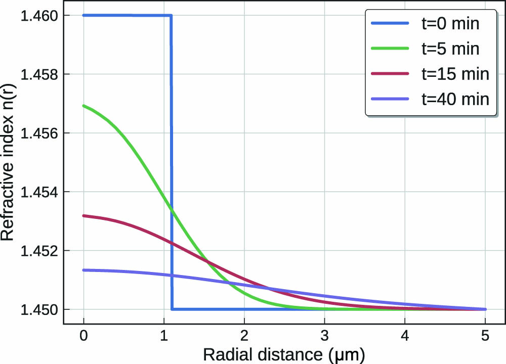
    Fig. 1. Simulation of refractive index distribution versus radial distance from the fiber core with different thermal expanding times.
    Diagram of fiber mode simulation by the finite element method. Fundamental mode with heating time at (a) T=0 min, (b) T=5 min, (c) T=15 min, (d) T=40 min, respectively. Comparing (d) to (a), the spot is increased by about seven times, and the Gaussian pattern shows that the fundamental mode propagating in the TEC fiber is maintained.
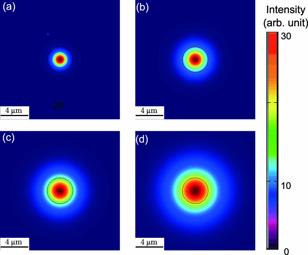
    Fig. 2. Diagram of fiber mode simulation by the finite element method. Fundamental mode with heating time at (a) T=0min, (b) T=5min, (c) T=15min, (d) T=40min, respectively. Comparing (d) to (a), the spot is increased by about seven times, and the Gaussian pattern shows that the fundamental mode propagating in the TEC fiber is maintained.
    Setup diagram of fiber core expansion. An SMF is held on the fiber mount and heated by a hydrogen/oxygen flame, and the beam profiler is used to monitor the spot size to determine the divergence of the beam after the TEC fiber, which finally indicates the MFD of the TEC fiber. The magnified inset is a photo of the target fiber in a fiber fusion splicer. It is a combination of an SM300 fiber and 630-HP fiber, where the length of the 630-HP fiber is controlled within 1 mm, and the heating region is focused on the splicing.
    Fig. 3. Setup diagram of fiber core expansion. An SMF is held on the fiber mount and heated by a hydrogen/oxygen flame, and the beam profiler is used to monitor the spot size to determine the divergence of the beam after the TEC fiber, which finally indicates the MFD of the TEC fiber. The magnified inset is a photo of the target fiber in a fiber fusion splicer. It is a combination of an SM300 fiber and 630-HP fiber, where the length of the 630-HP fiber is controlled within 1 mm, and the heating region is focused on the splicing.
    Spot changes when heating the splicing between the SM300 fiber and 630-HP fiber. (a) The initial SM300 with half-divergence θ=0.116 rad; (b)–(h) the spot change process; (i) the final Gaussian spot with half-divergence θ=0.033 rad. The 3.5-fold reduction in half-divergence is equivalent to a 3.5-fold increase in the MFD of the TEC fiber.
    Fig. 4. Spot changes when heating the splicing between the SM300 fiber and 630-HP fiber. (a) The initial SM300 with half-divergence θ=0.116rad; (b)–(h) the spot change process; (i) the final Gaussian spot with half-divergence θ=0.033rad. The 3.5-fold reduction in half-divergence is equivalent to a 3.5-fold increase in the MFD of the TEC fiber.
    (a) Mode matching efficiency between fiber and cavity mode for a symmetric concave cavity. The blue line shows the initial SM300 fiber for the FFPC, where the coupling efficiency is about 30% at the cavity length of 50 μm. The green line is the result after TEC treating; the efficiency can achieve 75% when the cavity length is 300 μm. (b) Mode matching between the fiber and cavity mode for a plano-concave cavity. Considering the flat end coupling with the cavity mode, as the dotted line shows, the initial fiber can form a stable cavity with coupling efficiency around 20%; when the MFD comes to 7.7 μm, the coupling efficiency can always be above 90%, as the solid line shows. The purple line shows that the coupling efficiency can be more than 95% with a large cavity length of around 400 μm.
    Fig. 5. (a) Mode matching efficiency between fiber and cavity mode for a symmetric concave cavity. The blue line shows the initial SM300 fiber for the FFPC, where the coupling efficiency is about 30% at the cavity length of 50μm. The green line is the result after TEC treating; the efficiency can achieve 75% when the cavity length is 300μm. (b) Mode matching between the fiber and cavity mode for a plano-concave cavity. Considering the flat end coupling with the cavity mode, as the dotted line shows, the initial fiber can form a stable cavity with coupling efficiency around 20%; when the MFD comes to 7.7μm, the coupling efficiency can always be above 90%, as the solid line shows. The purple line shows that the coupling efficiency can be more than 95% with a large cavity length of around 400μm.
    Xin-Xia Gao, Jin-Ming Cui, Yun-Feng Huang, Chuan-Feng Li, Guang-Can Guo. Thermal expanded core ultraviolet fiber for optical cavity mode matching[J]. Chinese Optics Letters, 2019, 17(9): 090601
    Download Citation