K. A. Tanaka1、*, K. M. Spohr1, D. L. Balabanski1, S. Balascuta1, L. Capponi1, M. O. Cernaianu1, M. Cuciuc1, A. Cucoanes1, I. Dancus1, A. Dhal1, B. Diaconescu1, D. Doria1, P. Ghenuche1, D. G. Ghita1, S. Kisyov1, V. Nastasa1, J. F. Ong1, F. Rotaru1, D. Sangwan1, P.-A. S?derstr?m1, D. Stutman2, G. Suliman1, O. Tesileanu1, L. Tudor1, N. Tsoneva1, C. A. Ur1, D. Ursescu1, and N. V. Zamfir1
1Extreme Light Infrastructure (ELI-NP) and Horia Hulubei National Institute for R & D in Physics and Nuclear Engineering (IFIN-HH), Str. Reactorului No. 30, 077125 Bucharest–M?gurele, Romania
2Extreme Light Infrastructure (ELI-NP) and Horia Hulubei National Institute for R & D in Physics and Nuclear Engineering (IFIN-HH), Str. Reactorului No. 30, 077125 Bucharest–M?gurele, Romania
K. A. Tanaka, K. M. Spohr, D. L. Balabanski, S. Balascuta, L. Capponi, M. O. Cernaianu, M. Cuciuc, A. Cucoanes, I. Dancus, A. Dhal, B. Diaconescu, D. Doria, P. Ghenuche, D. G. Ghita, S. Kisyov, V. Nastasa, J. F. Ong, F. Rotaru, D. Sangwan, P.-A. S?derstr?m, D. Stutman, G. Suliman, O. Tesileanu, L. Tudor, N. Tsoneva, C. A. Ur, D. Ursescu, N. V. Zamfir. Current status and highlights of the ELI-NP research program[J]. Matter and Radiation at Extremes, 2020, 5(2): 24402
Copy Citation Text
The emergence of a new era reaching beyond current state-of-the-art ultrashort and ultraintense laser technology has been enabled by the approval of around € 850 million worth of structural funds in 2011–2012 by the European Commission for the installation of Extreme Light Infrastructure (ELI). The ELI project consists of three pillars being built in the Czech Republic, Hungary, and Romania. This challenging proposal is based on recent technical progress allowing ultraintense laser fields in which intensities will soon be reaching as high as I0 ~ 1023 W cm?2. This tremendous technological advance has been brought about by the invention of chirped pulse amplification by Mourou and Strickland. Romania is hosting the ELI for Nuclear Physics (ELI-NP) pillar in M?gurele near Bucharest. The new facility, currently under construction, is intended to serve the broad national, European, and international scientific community. Its mission covers scientific research at the frontier of knowledge involving two domains. The first is laser-driven experiments related to NP, strong-field quantum electrodynamics, and associated vacuum effects. The second research domain is based on the establishment of a Compton-backscattering-based, high-brilliance, and intense γ beam with Eγ ? 19.5 MeV, which represents a merger between laser and accelerator technology. This system will allow the investigation of the nuclear structure of selected isotopes and nuclear reactions of relevance, for example, to astrophysics with hitherto unprecedented resolution and accuracy. In addition to fundamental themes, a large number of applications with significant societal impact will be developed. The implementation of the project started in January 2013 and is spearheaded by the ELI-NP/Horia Hulubei National Institute for Physics and Nuclear Engineering (IFIN-HH). Experiments will begin in early 2020.
I. INTRODUCTION
The era of modern-day high-power laser systems was instigated by the groundbreaking technological breakthrough of chirped pulse amplification (CPA) developed in 1986 by Strickland and Mourou,1 who were honored with the 2018 Nobel Prize in Physics for this work. At the Extreme Light Infrastructure for Nuclear Physics (ELI-NP) laboratory, facilities that are capable of supplying the highest focused laser intensity I0 are currently being implemented, characterized by light pulses in the petawatt (PW) regime lasting for tens of femtoseconds. Exploiting these highest human-made intensities, particles and γ photons will be produced that are characterized by hitherto unreachable quality parameters with regard to, for example, coherence, brilliance, and spectral features relating to the energy and time distributions of the induced radiations.2–6 Such intense beams are relevant to nuclear physics, allowing the exploration of new regimes, thus extending research based on traditional accelerator technology. ELI-NP aims to provide a flagship installation of a high-power laser system (HPLS) for the scientific community worldwide. The HPLS will consist of two independent laser arm segments, each providing a maximum power of 10 PW (1016 W). Also, a high-brilliance and high-intensity γ beamline called the Variable-Energy Gamma Ray (VEGA) system, which takes advantage of the Compton backscattering process, will be installed. At the HPLS, the acceleration of electrons to many tens of GeV within centimeter distances will be tested. Such high electron energies are currently only supplied by large RF-based accelerator systems. Secondary nuclear fission or fusion reactions on specific materials will also be investigated with the use of high-density beam bunches of energetic protons and heavier ions, potentially leading to the efficient production of medical radioisotopes and to improvements in nuclear-related diagnostic tools. Multistep reactions, such as fission–fusion, will be probed to address questions regarding the formation of the heaviest elements in the universe under stellar conditions. Furthermore, a new scheme of high-contrast X-ray imaging may be achievable for high-resolution medical observation. The HPLS at ELI-NP will also allow the study of how matter/antimatter may be produced out of pure vacuum by intense radiation fields. Moreover, materials and biological samples can be subjected to intense radiation fields to inform, for example, space mission applications.
The newly developed VEGA system at ELI-NP will be used to study key nuclear reactions relevant to nucleosynthesis, such as the fusion of α particles and carbon nuclei to produce oxygen (4He + 12C → 16O), which lies at the root of life on Earth. Furthermore, nuclear resonance fluorescence (NRF) measurements with the highest resolution can be undertaken with the intense, tunable beam of γ radiation of up to Eγ = 19.5 MeV. NRF-based novel technologies can also lead to a manifold of applications, for example, within imaging and γ tomography, potentially enhancing the field of nuclear security. In the following sections, descriptions of the two core facilities at ELI-NP, namely, the HPLS and the VEGA system, are given. The status of implementation of the ELI-NP facilities currently under construction is summarized. Concise technical descriptions are provided, together with some selected, high-priority, physics projects planned with the multi-PW lasers and the multi-MeV brilliant γ beam. Furthermore, some selected inaugural commissioning campaigns and newly developed instrumentation are discussed.
II. STATUS OF THE ELI-NP FACILITY 2018/19
A. Overview of the HPLS and the VEGA system at ELI-NP
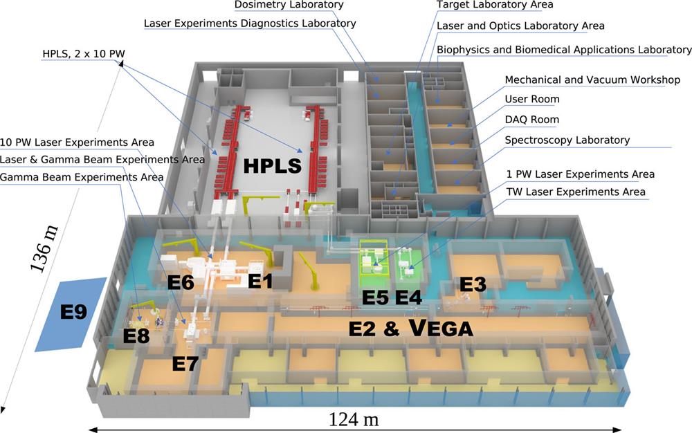
The HPLS was designed to serve the scientific cases suggested in the ELI-Whitebook published in 2010, thus pushing the boundaries of high-intensity laser-plasma research worldwide.7 To enable such research, the HPLS beams will be routed under vacuum to large custom-made experimental chambers in dedicated experimental target areas. A total of nine target areas named E1 to E9 are currently built. The laser system was installed by the Thales Group, a world-leading provider of state-of-the-art laser technology based in Paris and Romania. Final tests of the HPLS are being undertaken as of December 2019. The HPLS consists of three separated high-power beamlines with nominal peak of powers PHPLS = 100 TW, 1 PW, and 10 PW. All three beamlines have a dual-arm architecture and are fed by the central laser source. For achieving the high powers, an optical parametric chirped-pulse amplification (OPCPA) front end was implemented, which relies on state-of-the-art Ti:Sa crystals and dedicated pulse compressors. Coherent addition of the two strongest laser pulses from the two separated laser arms will result in powers larger than 20 PW. The layout of the whole experimental area at ELI-NP is depicted in Fig. 1.
Figure 1.Schematic overview of the HPLS and the VEGA system and associated target areas at ELI-NP. The two laser arms are depicted in red. The target areas E1, E4, E5, E6, and E7 show the 3D CAD designs of the target chambers currently under construction. The positions of the target areas E3, E8, and E9 associated with the VEGA system are indicated. The E9 area sits in the newly installed annex sketched by the blue footprint adjacent to the left side of the main building. The target area E2 will be facilitated for VEGA system-related experiments in the future.
Table I summarizes the core parameters associated with the driving laser source, which apply to all three different HPLS beamlines. In this table, λ0 denotes the range of the central wavelength and δλ0 its spread. τLP denotes the pulse duration, dfull the full diameter of the laser beam, S its Strehl ratio, and δarel the beam pointing stability.
λ0 (nm)
δλ0 (nm)
τLP (fs)
dfull (mm)
S
Contrast
δarel (μrad)
814–825
55–65
15–22.5
550
0.80–0.95
1 : 1013
≲3
Table 1. Laser system parameters shared by the three HPLS beamlines at ELI-NP.
Tests performed in early 2019 showed that the output energy for each of the three amplifiers in each arm can be expected to exceed the levels corresponding to the nominal powers PHPLS after compression.8 An in-depth publication of the measurement by Dancus et al. is forthcoming.9 A Strehl ratio S = 0.95 was confirmed in a test experiment with P = 3 PW. The HPLS systems are serving a total of five dedicated target areas E1, E4, E5, E6, and E7, as depicted in Fig. 1. Table II lists the core operational parameters associated with the three different HPLS. In this table, denotes the maximum achievable intensity after focusing with the appropriate mirror in a specific target station, ELP denotes the range of energies for a single laser pulse for which safe operation is guaranteed by Thales, and fLP denotes the pulse frequency. It is worth pointing out that the 10 PW system will allow one shot per minute.
PHPLS
ELP (J)
(W cm−2)
fLP (Hz)
Areas
Operational
10 PW
150–225
1023
0.017
E1, E6, E7a
2021
1 PW
15–25
5.6 × 10²¹
1
E1, E5, E6, E7b
2020
100 TW
1.5–2.5
2.2 × 10²⁰
10
E4
2020
Table 2. Operational parameters of the three HPLS beamlines at ELI-NP.
The laser beam transport system (LBTS) is the interface between the HPLS and the five target areas E1, E4, E5, E6, and E7. As sketched in Fig. 1, it allows the transportation of the laser pulses to the large experimental chambers under vacuum in a specific target area. The LBTS has several subsystems, which include laser beam turn boxes and the vacuum system. The turn boxes host large-aperture mirrors, and the vacuum system includes pipes, gate valves with a diameter of 80 cm, and pumps to secure the high vacuum along the laser pulse propagation path. Some of these structures are very detailed and are omitted in Fig. 1 for clarity. Implementation of the LBTS is going according to schedule, and the testing of the installed system started in November 2019. The two 10 PW beams are routed to each interaction chamber using a minimum number of mirrors to reduce the complexity of the system and the maintenance costs.
The pulses of the 100 TW HPLS are transported to the experimental area E4, where an experimental campaign is already in preparation to study the laser-induced damage threshold (LIDT) for mirror coatings irradiated with τLP ≲ 22.5 fs and ELP = 2.5 J. This will be the first experiment with the HPLS (March 2020). The 1 PW pulses are transported to the experimental areas E5 and, for commissioning experiments, to E7. The LBTS allows routing of the 10 PW pulses to the target areas E1 and E6, as well as also to E7 at a later stage of operation. For additional details related to the experimental target areas, including the scientific motivation and selected detector equipment, see Table III. In Fig. 1, the HPLS target areas E1, E6, and E7 are shown in white on the left of the figure. The first areas to be fully implemented, E4 and E5, which are served by the 100 TW and 1 PW arms of the HPLS, are displayed against a green background in the figure. The flat large-aperture mirrors and their corresponding motion systems allow high-resolution positioning of the beam at the entrance of an experimental chamber. Specific alignment and diagnostic devices provide the information that allows beam positioning within the LBTS. The LBTS control system enables routing of the beam and the operation of the vacuum. More details about the HPLS and LBTS have been reported in an earlier publication by Gales et al.6
HPLS: 100 TW
Area
Motivation
Detectors
Parameters
E4
Fundamental physics, QED-based elastic γ–γ scattering, search for weakly coupling sub-eV dark matter
Instrumentation to be developed
f/6
zR ≈ 70 µm
a0 ≲ 10
Table 3. Summary of the three HPLS at ELI-NP, including associated target station areas, summaries of the physical motivations, and selected detector equipment, as well as specific laser parameters. The detector equipment listed will be explicitly described in Table V (active detectors) and VI (passive detectors) in Sec. III.
The VEGA system is separate from the HPLS except for target area E7, where high-power laser pulses and high-intensity γ flashes up to 19.5 MeV with a very high linear polarization of >95% can be combined to allow nuclear experiments. The associated target areas E3, E8, and the newly installed E9 annex are also shown in Fig. 1.
B. The target areas at ELI-NP
The core parameters of the HPLS at ELI-NP, which are shared between all three beamlines present, are given in Table II, with the HPLS systems identified by their nominal power PHPLS. Table III gives a full overview of the five target areas associated with the HPLS and includes a brief summary of the scientific motivation as well as a selection of the related detector systems. Laser core parameters such as the focal number of the focusing mirror f, the diameter relating to 90% of the focal spot intensity , the associated Rayleigh length zR, and the maximum value achievable for the dimensionless laser parameter a0 are also provided. For E5, where the implementation of short- and long-focal-length mirrors is foreseen, both fs and fℓ are shown in Table III.
With the parameters given in Table III, one can deduce the range of intensities I0 achievable by an individual HPLS target area as presented in Fig. 2.
Figure 2.Nominal peak intensity ranges I0 as functions of the f number of the focusing mirrors installed at the target areas E1, E4, E5, E6, and E7 associated with the HPLS beams at ELI-NP. The solid lines describe the ideal case at the diffraction limit for which I0 is at its maximum value.
As mentioned before, target stations E3, E8, and E9 are solely dedicated to the VEGA system and are disjoint from the HPLS. Target station E7 is an exception, since the γ beam can be used for experiments in conjunction with the laser pulse from the 10 PW HPLS. Table IV gives a summary of the four target areas that are associated with the VEGA system at ELI-NP, briefly sketching the scientific motivation as well as highlighting a selection of detectors to be used in those areas. A more concise description of the selected detector systems will be given in Sec. IV (see Table VII). The associated maximum limit of Eγ is shown, as well as the expected full diameter of the γ beam, dγ.
Areas
Motivation
Detectors
Parameters
E3
Slow positron beamline for material science and characterization, structural and defect studies of metals, semi-conductors and insulators
Positron annihilation lifetime spectroscopy system (PALS), positron annihilation-induced Auger electron spectroscopy system (PAES)
Eγ ≤ 3.5 MeV dγ ≈ 6 mm
E7
γ-induced charged particle reactions for astrophysics and photofission experiments
Electronic time-projection chamber (ELITPC), array of twin Bragg ionization fission chambers (ELI-BIC), thick gas electron multiplier detectors (ELITHGEM)
Eγ ≤ 19.5 MeV dγ ≈ 0.75 mm
E8
γ-induced charged particle reactions for astrophysics and photofission experiments, NRF experiments with high-energy γ rays for basic and applied research
γ-induced reactions above the neutron threshold for basic and applied research
Moderated array of 3He tubes (ELIGANT-TN), array of liquid scintillators and lithium glass scintillators, large-volume LaBr3(Ce) and CeBr3 scintillators (ELIGANT-GN)
Eγ ≤ 19.5 MeV dγ ≈ 2.5 mm
Table 4. Summary of the target areas associated with the VEGA system, motivation, selected detector equipment, and specific parameters. The detector equipment shown will be explicitly described in Table VII in Sec. IV. The use of area E2 is yet to be decided.
III. INAUGURAL EXPERIMENTS WITH THE HPLS AT ELI-NP
High-power laser systems are at the dawn of a new era in accelerator technology, and efforts are concentrated on exploiting new acceleration regimes that efficiently transfer laser energy into particle and γ/X-ray beams at hitherto unmatched peak intensities I0. As the maximum achievable I0 is continually growing owing to technological advances, new routes for the scientific investigation of nuclear phenomena, particle and γ-ray source generation, and quantum electrodynamics (QED), as well as potential applications with societal impact, are being developed.4,10–12 At ELI-NP, two experimental areas E1 and E6, are fully dedicated to this research, and both will be capable of utilizing two laser beams with a power of up to 10 PW each.13 Before their installation is finished, initial tests relating to the research summarized above will be carried out at the 1 PW beamline at E5.
The commissioning experiments are aimed at investigating ion acceleration and QED effects via the generation of ultraintense particle and γ-beam flares.6 The associated scaling laws governing these regimes will be deduced in analogy to the work presented by, for example, Fuchs et al.14 Moreover, the theoretical predictions obtained using particle-in-cell (PIC)-based codes15 can be evaluated. Achieving maximum kinetic proton energies around and above 200 MeV with minimized energy spread δEp is one of the core aims envisaged in the commissioning campaign. This research will naturally progress by studying different acceleration regimes to optimize secondary ion sources for various applications, with particular emphasis on nuclear physics.16 If the predicted results are attained, a new era in acceleration technology will begin, as envisaged in the original paper by Veksler17 more than 60 years ago. Additionally, to spearhead the development of ultraintense laser-driven γ-ray sources, the optimization of the laser (energy)-to-γ-radiation conversion based on the onset of QED effects is of paramount interest in the inaugural campaign. Furthermore, the production of intense ultrarelativistic electron and positron beams and of coherent betatron radiation will be extensively studied.
A. Theoretical considerations
1. Ion acceleration
The complexity of the laser–matter interaction encompasses a manifold of ion acceleration regimes distinguishable by a set of parameters. For the HPLS, these are its intensity I0, the related pulse duration τLP, and its temporal profile. The most crucial parameters relating to the target are its electron density ne and its thickness ℓT. In the last two decades, several acceleration regimes have been experimentally identified. Additionally, the existence of further, very exotic regimes is predicted based on PIC simulations. The laser intensity I0 is often represented using the dimensionless laser amplitude a0. Its value for linear polarization is given bywith e and me the electron charge and mass, and c the speed of light in vacuum. Furthermore, E0, λ0, and ω denote the maximum electric field amplitude, wavelength, and angular frequency of the laser, respectively.18 Depending on the acceleration mechanism, the target thickness ℓT or the dimensionless areal density σ = neℓT/ncrλ is used to describe the scaling laws. Figure 3 illustrates the acceleration regimes based on current measurements and simulations. The most prominent regimes that can be studied at ELI-NP are the target normal sheath acceleration (TNSA),19 the Coulomb explosion (CE),20 and the radiation-pressure-dominated acceleration (RPDA).16,21 As of today, TNSA is the most extensively studied regime. Within this regime, the laser light is interacting with the front side of the target and generates relativistic electrons that can cross the target bulk, setting up a plasma sheath, which generates a strong electric field between the electron cloud and the target surface. For extremely high laser intensity, under suitable conditions of laser–matter interaction, RPDA can dominate the acceleration process by means of the so-called hole boring (HB) or light sail (LS) mechanisms for thin target foils. In that case, the electrons are pushed forward during the first laser cycle owing to the radiation pressure, and the ions respond promptly to this charge displacement and the associated strong E field. This generates synchronous motion between electrons and ions, making the target bulk “fly” and accelerate continuously during the laser push, even reaching relativistic velocities (“relativistic flying mirror”). In this instance, most of the laser energy is efficiently transferred to the target ions. The maximum kinetic energy per nucleon with n nucleons, Em/n, for such an ideal laser–target coupling can be expressed aswhere mpc2 is the proton mass–energy equivalent of 931.5 MeV, with c being the speed of light, σ is the areal density of the target, and F is the total laser fluence, i.e., the laser pulse energy ELP divided by the laser focal spot area.11
Figure 3.Regimes of laser-driven ion acceleration with Coulomb explosion (CE), target normal sheath acceleration (TNSA), and radiation-pressure-dominated acceleration (RPDA). The gray line indicates the opaque/transparent border and the dashed line the target thickness ℓT for which the proton energy at a given I0 will be maximal. The regimes overlap in certain parameter regions. Intensity conditions, as indicated by the green arrow, should be reachable with the ELI-NP 10 PW HPLS, employing self-supporting targets as thin as 10 nm. The regimes as depicted in this figure follow published work by Daido et al.18
For targets of limited length, typically smaller than the laser wavelength λ0, CE will take place. If the laser is intense enough to expel all electrons from the region of interaction, then only a bare ion core is left. The electrostatic field created by the space charge then leads to a CE. This field is the most intense that can be generated under any electron–ion charge displacement conditions. This process can be best realized by employing small clusters such as those created by a low-temperature gas jet. It is important to note that the borders among these regimes are not sharp, and hybrids exist. Moreover, for ultrathin foils (e.g., of the order of tens of nanometers), the onset of relativistic induced transparency (RIT) has to be considered if I0 ≳ 1021 W cm−2 where RIT occurs owing to the relativistic increase in the inertia of the electrons (m′e = γme), which decreases the plasma frequency ωp, thus increasing the plasma critical density.22–24 The lower density acts like an aperture in the target, and strong electric and magnetic field amplitudes of the order of E0 ∼ 50 TV m−1 and B0 ∼ 0.5 MT enable laser pulse propagation throughout the plasma. This, in turn, enhances and, at the same time, reduces the energy spread of the beam.25 As a tradeoff related to RIT, the overall conversion efficiency εconv is limited, since the momentum transfer from the pulse to the foil is optimal for opaque conditions. Recently, enhancement of due to RIT has been experimentally shown by Higginson et al.,26 who achieved 100 MeV within a hybrid TNSA–RIT scheme. This value is currently the record for laser-accelerated ions.
To estimate the proton energy at ELI-NP achievable in the commissioning experiments with the 10 PW systems that can provide an intensity I0 ∼ 1023 W cm−2 (i.e., a0 ∼ 220), PIC2D simulations were performed (using the Epoch code27) for a solid target with ℓT = 800 nm. The results are depicted in Fig. 4, which shows the proton and γ-ray spectra as well as the spectrum for fully ionized carbon ions for a CH2 target with ℓT = 800 nm irradiated at I0 = 1023 W cm−2.
Figure 4.Energy spectra of protons (black), C6+ (green), and γ radiation (red) emitted in the direction of pulse propagation according to a PIC2D-based Epoch code28 including QED effects. A circularly polarized laser beam of intensity 1023 W cm−2 and a fully ionized CH2 target with ℓT = 800 nm were assumed.
If correct, the commissioning experiments should lead to a maximum proton energy 400 MeV exhibiting the typical Maxwell–Boltzmann distribution as shown in Fig. 4. The total efficiency of laser-to-γ conversion in the region is estimated to be around 14%. In these calculations, no preplasma modeling was included. A substantial amount of the related high-energy γ radiation will be emitted in a backward direction with respect to the incident laser beam propagation axis.
Investigations in the CE regime facilitating the gas target station at E6 are predicted to result in similar energies. Esirperkov et al. give a scaling lawwith Zion being the charge of the accelerated ion and PLP/PW the power of the laser pulse in units of petawatts.16,18Figure 3 illustrates various ion acceleration regimes as a function of the target thickness (horizontal axis) and the laser intensity (vertical axis).
2. Ultrarelativistic electron acceleration
The generation of ultrarelativistic electrons via laser wakefield acceleration (LWFA) is an important new field of plasma physics, both as a tool for testing QED theory and for applications involving leptons and γ rays. Since the original idea of Tajima and Dawson,29 a lot of research has been dedicated to studying different electron acceleration mechanisms.30 Nowadays, most LWFA experiments are based on wave-breaking, or self-injection, where the electrons are injected into the wave. There are also some other injection schemes that do not rely on self-injection.31 Using the so-called “bubble” regime, it has been shown that quasi-monoenergetic electron beams can be produced in bunches of tens of femtoseconds. The accelerating field generated in the wake is of the order of 100 GeV m−1, and the electrons can be accelerated for many centimeters, if the prevailing interaction conditions are ideal. The experimental area E6 will be dedicated to generic electron acceleration studies first, followed by QED experiments. The two laser arms of the HPLS are focused by a long-focal-length (32 m) spherical mirror with ∼f/54 and a short-focal-length (2 m) parabolic mirror with ∼f/3.5. The long-focal-length mirror will be used to generate the electron beam, while the short-focal-length mirror will be used to shoot a counterpropagating second laser pulse against the electrons beam, providing the conditions for entry into the strong-field QED regime.32 The commissioning experiments at E6 will be dedicated to the generation of stable multi-GeV electron beams with high charge exhibiting a quasi-monoenergetic distribution. As shown in Table III, each 10 PW laser arm has an energy of ∼225 J and a pulse duration τLP ≲ 22.5 fs. However, with a focusing mirror of ∼f/54, the optimum LWFA conditions require a longer pulse (namely, ∼100 fs). Therefore, there is a need to stretch the laser pulse. An optimal acceleration can produce electron beams of energy in excess of 5 GeV, over an acceleration distance greater than 10 cm.33 The beams will be diagnosed by a permanent magnetic spectrometer for electron and positron detection. The gas cell will be probed optically by interferometry and shadowgraphy with an ultrashort laser beam, and the electron bunch charge and the betatron emission will be measured as well. Further, after the interaction, the laser pulse will have residual energy, which will give a flux of the order of 1015 W cm−2 at a distance 10 cm away from the gas target. This value exceeds the damage threshold of any material. Hence, a metallic foil will be employed as the laser beam dump. An electron beam dump for electron energies Ee > 5 GeV will also be utilized in the region near the GeV e− spectrometer.
3. Laser-to-γ conversion
According to theory, the distribution of the initial laser energy ELP between ion acceleration, e− acceleration, and γ radiation/X-rays changes dramatically with increasing laser intensity represented by a growing a0. It is calculated that laser-to-γ conversion will be dramatically enhanced. This is due to the onset of nonlinear Thomson scattering in the QED regime wherein the energy of the photons Eγ is given by . For a0 ≈ 220, the maximum photon energy Eγ is in the hundreds of MeV energy range.34 Hence, strong coupling between the laser pulse and the solid matter in which the pulse propagates can be assumed. Moreover, the onset of radiation friction leads to self-focusing patterns via magnetic fields. This, in turn, limits the transverse phase space of the electrons and traps them efficiently in the laser-produced channel, where they undergo betatron oscillation imposed by the quasistatic electromagnetic fields.35 The radiation is partially coherent, showing a significant broadening of the resonance condition and an exponential shape. For an initial laser power raising from 1 PW to 10 PW, the conversion efficiency from laser to γ rays can increase rapidly from a few percent to εγ ∼ 30% for a target made of light ions, as predicted by PIC simulations.36 For such conditions, the 10 PW system can be seen as an ideal transformer from light into γ radiation. The calculations also show that the high-energy photon part of the photon beam can reach more than 100 MeV, being aligned either parallel or antiparallel to the propagation direction of the laser. Besides a0, the atomic mass mi of the production target is a crucial parameter in the related theoretical evaluations for I0 > 1022 W cm−2. For Eγ < 20 MeV, the radiation pattern becomes more and more isotropic. γ flares are predicted to have a maximum yield in the backward direction if heavy-ion production targets are used.37 For optimization of the γ yield, preplasma engineering is required.
The use of a tailored overcritical-density target for which the laser pulse to γ-ray energy conversion efficiency is substantial is mandatory. With I0 ≈ 1023 W cm−2, a peak brightness of nγ ≳ 1025 ps−1 mm−2 mrad−2 (1% BW)−1 at 15 MeV should be achievable with the ELI-NP 10 PW arms in the commissioning experiments.
B. Experimental considerations and diagnostics
The design strategy for the HPLS at ELI-NP followed the necessity to separate solid and gas target stations as debris mitigation, and nuclear shielding requirements differ substantially depending on the nature of the target and the produced radioactive radiation (see Table III). Hence, the E1 target chamber at ELI-NP is dedicated solely to the study of laser-plasma interaction with solid targets, while the E6 chamber, similar in dimensions, is exclusively for gas targets. At E1, one has to consider the measurement of fast ions, electrons, and neutrons, as well as high-intensity γ flares, while equipment at E6 has mainly to be aligned to handle relativistic electrons and the highest photon fluxes. Furthermore, to protect the off-axis parabolic mirror and the HPLS, a sacrificial plasma mirror system is expected to be installed in E1 just a few centimeters away from the front of the primary production target. For long-term development, the introduction of circular polarization (CP) is suggested, since it helps to reduce J × B electron heating, which otherwise would lead to more rapid deterioration of the target and de-optimize the acceleration process. Both target stations are connected to the two 10 PW HPLS arms and can also source the two 1 PW HPLS arms used for inaugural studies.
Since ELI-NP, like all other HPLS, operates in a high-intensity, low-repetition-rate mode, one has to implement a new strategy for the diagnostics to record the manifold nuclear phenomena induced by short-pulsed intensive particle and radiation beams. Moreover, to understand the different acceleration and conversion processes, laser and plasma characterization will also be performed in situ with optical probing techniques on a shot-to-shot basis. A particular challenge is given by the fact that the time scales for beam production are in the femtosecond regime and much shorter than the typical pulse shaping and acquisition times of any electronically based detection system.
For all the related development, special attention has to be given to the expected strong background caused mainly by bremsstrahlung. The associated noise will lead to a gamut of soft and hard X rays, which will make the greatest contribution to the unwanted background signal on pulse impact. Direct reactions from the produced ions and neutrons may also introduce a coinciding nuclear radiation background. To account for those instances, in line with radioprotection considerations and detector and shielding design optimizations, Fluka38 simulations were undertaken to evaluate the radiation levels expected at the E1 and E6 target chambers and to optimize the signal-to-noise ratio (S/N) for each detector. Another noise-enhancing factor is the unavoidable induction of an electromagnetic pulse (EMP) generated by the laser–matter interaction.39 An ELI-NP study by Meade40 concluded that, to first order, the EMP-induced background scales linearly with the energy ELP of the laser pulse and is proportional, to a lesser extent, to I0. Owing to the high background level and the diverse background sources, the detector systems are foreseen to facilitate optical readouts via fiberglass cables, which feed into high-resolution cameras placed outside the interaction chamber. As for the ion generation studies, a 1013 suppression of the prepulse is guaranteed by Thales. To minimize the intruding effects of the prepulse formation even further, a thin plasma mirror system using a film with a thickness of ℓ ≈ 10 nm will be tested.
1. Diagnostics development and nuclear detector systems
Since no laser-plasma interactions with a 10 PW system and intensities of I0 ∼ 1023 W cm−2 have ever been measured, the design of robust nuclear diagnostic tools has to be based solely on simulations and the extrapolation of existing measurements, for which intensities are about one full order of magnitude smaller. Over a decade ago, Chen et al.41 summarized suitable detection systems for laser-plasma experiments with I0 ≲ 1020 W cm−2, providing a benchmark to follow for the ELI-NP implementation. For the commissioning experiments, the energy ranges and the corresponding energy resolution for the currently existing standard particle and photon detector systems need to be extended. This translates into, for example, estimating a value for S/N and guaranteeing fail-safe operation of the detectors, as well as protecting the HPLS. Besides that, a characterization of the laser pulse at a full-power shot, before and after the interaction with the target, will be done, as well as measurement of the plasma density using interferometry. In the following paragraphs, a selection of core detection and diagnostic devices to be used in E1, E5, and E6 are presented. It is worth noting that their design is still being optimized, and their exact positioning in the target station will have to be decided on an experiment-to-experiment basis. A precalibration of specific detectors will be undertaken at an RF-based accelerator system, such as a linear accelerator (LINAC) before the commissioning laser experiments take place. At this very moment, all instrumentation introduced is being developed, and Technical Design Reports (TDRs) are currently being finalized, with purchase tenders released. The construction of the instrumentation and the calibration measurements are on target for completion on schedule. Most of the performance parameters presented are based on simulation programs, such as Geant4, Simion, and Fluka.38,42,43 A summary of active, passive, and optical detection systems depicted in this section is given in Table V for the active and Table VI for the passive detectors.
Detector and purpose
Areas
Parameters
Thomson parabola: For energy spectra of ions
E1, E5
OP: Ion deflection in static field |E| = 26 kV cm−1 and |B| = 1.0 T; Ep ≲ 250 MeV (E5: ≲ 100 MeV); δEp ≲ 1.6 MeV (E5: ≲ 0.8 MeV); S/N ≳ 3 db; Ωgeo(1.5 m) = 1.5 × 10⁻⁸ sr. Dimensions: 10 cm × 20 cm × 100 cm. Weight: 220 kg. Shielding: Encased Pb: 8 cm at front; 3 cm at sides, back and top. No.: ≤3. Readout: Optical, LANEX screen.
Gamma spectrometer: For γ-radiation up to Eγ = 50 MeV
E1, E5
OP: Conversion of γ radiation with Li target, measurement of diametrically deflected e−–e+ pairs with opposing LANEX screens, deflection via a magnetic field with |B| = 0.5 T; Eγ = 5–50 MeV; δEγ ≤ 20%; S/N ≳ 10 db, ɛtot = 10−8–5 × 10⁻⁸. Dimensions: 35 cm × 35 cm × 60 cm. Weight: 380 kg. Shielding: Encased Pb: 30 cm at front, 2 cm Fe at sides, back and bottom. No.: 1. Readout: Optical, LANEX screen.
e−–e+ spectrometer: For e− up to 100 MeV
E1, E5
OP: Measurement of e− and e+ after deflection by magnetic field (|B| = 0.8 T) with LANEX screens, identical build to gamma spectrometer (but without Li converter); Eγ = 5–100 MeV; δEγ ≤ 5%; S/N ≳ 10 db. Dimensions, Weight, Shielding, No., Readout: Identical to gamma spectrometer.
CsI(Tl) gamma spectrometer: For γ-radiation up to Eγ = 20 MeV
E1, E5
OP: Measurement of segmented scintillation units, 10 layers of 5 mm thick CsI(Tl) scintillation layers, energy spectrum of γ radiation estimated after deconvolution of measured spectra; Eγ = 2–20 MeV; δEγ ∼ 30%–40%. Dimensions: 20 cm × 15 cm × 15 cm. Weight: 20 kg; Shielding: Encased Pb-canvas ∼1.5 cm. No.: 5. Readout: Optical from scintillator units.
GeV e− spectrometer: For e− up to 5 GeV
E6
OP: Measurement of e− deflection by magnetic field of |B| = 1 T with LANEX screen; Eγ = 100 MeV–5 GeV; δEγ ≲ 10%; ΔΘ = ± 10 mrad. Dimensions: 36 cm × 25 cm × 80 cm (dipole). Weight:680 kg. No.: 1. Readout: Optical, LANEX screen.
Table 5. Summary of active detectors in the target areas E1, E5, and E6 to be used in inaugural commissioning experiments facilitating the HPLS.
OP: Measurement of γ- or proton-induced nuclear reactions such as (γ, xn) or (p, n) exit channels. Isotopes for γ-induced reactions are 181Ta, resulting in (γ, n) and (γ, 3n) channels with t1/2(180Ta) = 8.15 h and t1/2(178Ta) = 2.36 h, as well as12C and63Cu, resulting in (γ, n) channels with t1/2(11C) = 20.36 min and t1/2(62Cu) = 9.67 min. For proton energy, e.g., the reaction63Cu(p,n)63Zn with t1/2(63Zn) = 38.47 min will be used; typical Ωint ≲ 1 sr. Weight: 1 kg. No.: 5–10. Readout: Offline with HPGe or NaI
RCF, image plates, and CR-39: For γ and ion energy spectra and radial distribution
E1, E5
OP: Measurement of γ- and ion-induced darkening of RCF or image plate fluorescence or traces within CR-39; Eγ is adjustable with attenuator stacks; typical Ωint ≲ 1 sr. Weight: 1 kg. No.: 5–10. Readout: Optical with high-resolution scanning system
Optical plasma probe: For probing
E1, E5, and E6
OP: Probing plasma electron density with fundamental λ0 and second-harmonic wavelength at ∼410 nm. No.: 1. Readout: Optical (interferometry, shadowgraphy)
Table 6. Summary of the passive and optical detector systems in the target areas E1, E5, and E6 to be used in inaugural commissioning experiments facilitating the HPLS.
A rendered view of a potential experimental arrangement in the E1 target station is given in Fig. 9. The gamma spectrometer and the e−–e+ spectrometer are placed at 30° to the target normal, while the Thomson parabola to the left is looking at the direction of laser propagation. The CsI(Tl) detectors are not depicted. The inner dimensions of the reaction chamber are 4.0 m × 3.3 m × 1.8 m.
Figure 9.Proposed setup of the diagnostic detectors for a typical commissioning experiment at E1, showing the envelope of the Thomson parabola (TP) in blue close to the left target wall, as well as the gamma spectrometer (GS) and the e−–e+ spectrometer (e−–e+S), which are placed facing the interaction point in the primary target in the vicinity of the middle of the chamber. The laser pulse envelope is shown in light red, with the focusing f/2.7 parabolic mirror on the lower left. The green (tube-)line indicates the light path associated with the optical plasma probing arrangement. The yellow circles on top of the gamma and e−–e+ spectrometers indicate the connecting points for the optical fibers to be used for the readout.
The E6 chamber will have the shape of a rectangular parallelepiped with the same spatial dimensions as the E1 chamber. The target will be a gas jet or a gas cell about 10 cm long. The interaction of the gas target with the long-focal-length laser beam will produce multi-GeV electrons, which will be diagnosed by a permanent dipole magnet and scintillator screens. The gas target will be probed by an optical probing system using a laser beam with a wavelength in the fundamental or second harmonic of the main laser and a pulse duration of ≲22.5 fs. Laser beam diagnostics will also be present to have a better understanding of the interaction processes. A laser beam bump will be placed at about 10–30 cm away from the exit of the gas cell and reflected off the main interaction chamber to stop the laser beam propagating further toward the chamber wall.
IV. HIGHLIGHTS OF THE INAUGURAL EXPERIMENTAL PROGRAM AT VEGA
ELI-NP will construct a γ-beam system called VEGA that will be able to provide γ-ray beams with energies up to 19.5 MeV and a high degree of linear polarization of >95%. The production of the quasi-monochromatic γ beam is based on the inverse Compton scattering process in which the laser light pulses are scattered off relativistic electron bunches. The VEGA system at ELI-NP will become one of the state-of-the-art facilities for delivering γ beams with photon spectral densities and bandwidths orders of magnitude better than current technology allows.
A versatile experimental research program is under preparation for the VEGA system. The experiments will focus on different aspects of photonuclear physics and aim to exploit to the full extent the unique performance characteristics of the VEGA system, such as the narrow bandwidth of the beams, their high brilliance, and their high degree of polarization. Different aspects of the γ-beam-related research program have been reviewed recently in a series of works.6,61,62 In the following, several important studies within the scope of this research program are highlighted. They are related to different fields in photonuclear physics, such as NRF, photonuclear reactions, studies of nuclear resonances, and photo-fission research. NRF utilizes pencil-like, narrow-bandwidth, highly polarized γ beams with a spectral photon density of around 104 s−1 eV−1. This enables NRF experiments with higher sensitivity and improved yield, and minimizes the mass of the targets, which, in most cases, will consist of very expensive, isotopically enriched materials. Thus, at ELI-NP, it will be possible to use targets made from only a few hundred milligrams of material, which opens an avenue for studies of less abundant isotopes, such as p-process nuclei or actinides. Note that, so far, there have been very few NRF studies in the actinide region, such as for 232Th or 236,238U.63
To perform these studies, the ELI-NP Array of Germanium Detectors (ELIADE)64 is currently under construction at ELI-NP. It consists of eight HPGe clover detectors of TIGRESS type.65 The detectors are arranged in two rings, each ring having two detectors in the vertical plane and two in the horizontal plane. Each clover detector consists of four encapsulated n-type HPGe crystals, which are manufactured from a crystal with a diameter of 60 mm and a length of 90 mm. The outer surface of each crystal is tapered over 30 mm from the front of the crystal to allow close packing. The core contact has a diameter of 10 mm and a depth of 75 mm. Each crystal is divided into four quadrants and two lateral sections via an outer boron-implanted contact. Thus, nine signals are read for each crystal, resulting in 36 signals per detector and a total of 288 electronic channels for the HPGe array. Also, for the measurement of high-energy γ rays, bismuth germanate (BGO) scintillators will be mounted as back plugs to suppress background noise. Large LaBr3(Ce) detectors can be mounted in positions at 45° with respect to the HPGe clover detectors. This arrangement will increase the overall efficiency of the array. As of Autumn 2019, all detectors and electronics have been delivered and tested at the ELI-NP premises. Mechanical support and the liquid nitrogen cooling systems of the array are under construction, and a data acquisition system (DAQ) has been implemented and tested. A 3D CAD view of ELIADE is presented in Fig. 10. In the shown configuration, the array will have an absolute γ-ray efficiency of ∼6% and will enable coincidence measurements as well as serving as an excellent γ-ray polarimeter and thus providing opportunities for studies of γ-ray angular correlations.
Figure 10.A 3D CAD view of the ELIADE array with the HPGe detectors shown in gray. The supporting frame is shown in blue. The voids in the frame can be equipped with LaBr3(Ce) detectors for selected experimental campaigns. The pipe for the incoming beam is shown in pink. Courtesy of A. Imreh.
For the commissioning NRF experiment, one considers the photoactivation measurement of 180Ta.6 An important part of the ELIADE research program concerns high-resolution studies of E1, M1, and E2 modes in the region below the neutron evaporation threshold of nuclei. It will be possible to distinguish and separate different excitations in the overlapping region of the pygmy dipole resonance (PDR), the giant dipole resonance (GDR), the magnetic dipole resonance (MDR), and the pygmy quadrupole resonance (PQR). The γ-ray efficiency of ELIADE will provide an opportunity to measure details of the γ-ray decay of such excitations, for example, the ground-state decay vs the decay to excited states. Such studies will inform theoretical models aimed at describing pygmy resonances in atomic nuclei. The experiments will be sensitive to weak branches of different excitation modes. For example, the electric dipole polarizability αD is very sensitive to the low-lying E1 strength, and is correlated to the neutron skin thickness in a robust and less model-dependent manner.66–69 These theories connect the slope of the symmetry term of the nuclear equation of state (EoS) to the neutron skin thickness. The polarizability αD is related to the photoabsorption cross-section σabs by70,71where E denotes the excitation energy and σabs the absolute cross-section. Note that αD depends strongly on the E1 strength at low energies. For the stable nucleus 208Pb, the neutron skin thickness was extracted from the measured αD.72 Such experiments will be performed with higher sensitivity at the VEGA system with the ELIADE array.
A. Experiments above the particle evaporation threshold
An array of large-volume scintillation detectors consisting of 15 LaBr3: Ce crystals (3 in. × 3 in.) coupled with Hamamatsu R11973 photomultiplier tubes (PMTs) and 19 CeBr3 crystals (3 in. × 3 in.) coupled with Hamamatsu R6233 PMTs is under construction at ELI-NP. This array will be combined with 37 EJ301 liquid scintillator neutron detectors and 25 GS20 6Li glass detectors, called the ELI Gamma Above Neutron Threshold Gamma Neutron (ELIGANT-GN).73,74 The detectors will be placed at backward angles, as demonstrated in the 3D CAD design of the array in Fig. 11. The LaBr3(Ce) detectors are mounted on a frame 30 cm away from the target. The neutron detectors are mounted on movable mechanical structures, allowing a maximum distance of 1.5 m from the target, which is sufficient for the time-of-flight (ToF) separation of the neutrons. The array will provide the possibility for measurements of single and coincidence γ-ray events with the LaBr3(Ce), single-neutron (n) events in the EJ301, and GS20 detectors and coincidence γ–n in the γ and neutron detectors. The first experiments will target the ground-state γ decay of the GDR and the PDR, as well as studies of two-step γ decay through low-lying states. These can be combined with measurements of the (γ, n) branch, providing precise data for the branching ratios. Detailed Geant4 simulations of the performance of the ELIGANT-GN array, a study of the response of the lanthanum bromide, and the EJ301 liquid scintillator detectors, as well as beam-time estimates, are provided in the work by Krzysiek et al.74 Planned commissioning experiments address, for example, a study of the E1 strength of 208Pb.6,67,74,75
Figure 11.A 3D CAD view of the ELIGANT-GN array. The lanthanide bromide detectors are mounted in the inner frame (green). They cover the bottom half of the full sphere angles and are placed inside the outer frame (yellow) supporting the neutron detectors. These detectors cover the upper half of the sphere and are depicted in gray (the small red circles show the junctions with the coupled PMTs). The beam pipe emerging from the lower left of the figure is shown in pink. Courtesy of A. Imreh.
Measurements of cross-sections of photoneutron reactions will be done with an array of 30 3He counters embedded in polyethylene, which serves as a moderator for thermalization of the neutrons.73 The array, which is called ELI Gamma Above Neutron Threshold Thermal Neutrons (ELIGANT-TN), is designed such that it has a flat efficiency of about 38% below En = 3 MeV and dropping to about 35% at higher energies up to 5 MeV. More than 90% of the neutron spectrum stays in the flat region, which allows cross-section measurements with an uncertainty <1%, as demonstrated in experiments with a similar device at the NewSubaru facility.75 Furthermore, the average neutron energy can be extracted using the ring ratio method.76 A commissioning study with ELIGANT-TN will be the measurement of the photodisintegration of 9Be,6 for which data from different measurements are in disagreement.77–79 The experimental program at the VEGA system at ELI-NP aims further to also cover other aspects of photonuclear physics, such as photofission80 and studies of photonuclear reactions that coincide with the emission of charged particles.81 For realization of these experiments, different instruments will be available at ELI-NP. In particular, for photofission, two detector arrays are under construction, the ELI Bragg Ionization Chamber (ELI-BIC) and the ELI Thick Gas Electron Multiplier (ELITHGEM) arrays,6,80 which will be used for measurements of photofission cross-sections and of mass, charge, angular, and kinetic energy distributions. Moreover, the occurrence of processes with very low cross-sections, such as transmission resonances,82 highly asymmetric fission, clusterization phenomena, and triple fission, is foreseen.
The envisaged studies of charged particle photonuclear reactions are related to key nuclear astrophysics reactions, such as the 16O(α, γ)12C reaction. The physics case for these studies is discussed at length in Refs. 6 and 81. Two state-of-the-art instruments are under construction at ELI-NP: a time-projection chamber called the ELI Time Projection Chamber (ELITPC),83,84 with a readout based on gas electron multiplier (GEM) technology, and a 4π array of silicon strip detectors called the ELI Silicon Strip Array (ELISSA).81 In addition, an applied physics program for material characterization studies will be carried out, facilitating a dedicated slow-positron beamline named ELI Positron Source (ELIPS). A concise summary of the detector systems introduced in this section is given in Table VII. The notation in the “Parameters” column is the same as that in Table V, with the addition of fmax describing the maximum frequency a detector system can cope with, δxp,α denoting the uncertainty in the determination of the lateral position for protons, and α and δt(FWHM) denoting the full width at half maximum of the time resolution.
B. Probing the microscopic structure of nuclear excitation modes at ELI-NP
With the unique possibilities provided by the VEGA system at ELI-NP, nuclear theory will have the opportunity to be informed by high-resolution data stemming from photon-induced excitations and reactions.
In this respect, one of the most exciting achievements of modern nuclear structure physics is the observation of two new excitation modes at low energy, namely, the PDR85 and its higher-multipole extension the PQR,86–88 both of which reveal novel aspects of the dynamics of isospin-asymmetric nuclear matter. In these findings, an enhanced electric dipole or quadrupole strength, respectively resembling a resonance structure below or close to the neutron emission threshold, was detected as a standard feature of stable and unstable nuclei with neutron excess. It was associated with oscillations of a small outer layer of neutron-rich nuclear matter with respect to the isospin-symmetric nuclear core.
From systematic studies of nuclear isotonic and isotopic chains, a correlation of PDR and PQR strengths and nuclear-skin thickness was found, and the connection of PDR and PQR to oscillations of weakly bound nucleons at the nuclear surface was further confirmed by analysis of nuclear ground states and neutron and proton transition densities.86,89,90
During the last few years, the PDR has been the subject of many experimental and theoretical investigations.85,91,92 However, most theoretical studies of the PDR have been limited to the quasiparticle random-phase approximation (QRPA), which cannot explain in detail the experimental data on low-energy dipole excitations and the PDR fragmentation pattern. For that purpose, an extended approach based on energy density functional (EDF) plus three-phonon quasiparticle phonon model (QPM) theory89,90,93 has been developed that explicitly accounts for the interactions beyond particle–hole (p–h) configurations. In particular, the QPM formalism allows for further expansion of QRPA p–h excitations to multiparticle-multihole states in terms of coupling between quasiparticles and phonons.94 Thus, for spherical even–even nuclei, the model Hamiltonian is diagonalized on an orthonormal set of wave functions constructed from one-, two-, and three-phonon configurations:95where R, P, and T are unknown amplitudes and ν labels the number of the excited state. The electromagnetic transition matrix elements are calculated for transition operators, including the interaction of quasiparticles and phonons,96 where exact commutation relations are implemented, which is a necessary condition to satisfy the Pauli principle.
Presently, the above is one of the most elaborated theoretical method allowing a unified description of low-energy single- and multiple-phonon states and the GDR. Besides, an important advantage of QPM compared with other methods involving quasiparticle–phonon coupling is the use of large configuration spaces,97 which is of great importance for quantitative descriptions and predictions of nuclear data.
Spectral distributions of low-energy E1 and M1 strengths below the neutron threshold in 206Pb (Sn = 8.087 MeV) have recently been studied,97 and the results are shown in Fig. 12. It is found that the low-energy E1 and M1 strength is strongly fragmented. In the E1 case, this is due to the interaction of the p–h QRPA states from the PDR and those from the GDR tail and also interactions with multiphonon configurations with different spin and parity. A detailed EDF + QPM analysis of the E1 transition matrix elements strongly suggests that the PDR or the neutron skin oscillations dominate the distribution of the dipole strength up to about 7 MeV, at which point the tail of the GDR starts to make an important contribution.97 Overall, the PDR and the GDR account respectively for about 77% and 12% of the E1 strength below the neutron separation energy in 206Pb. Also significant is the impact of multiphonon states on the total E1 strength and, to a lesser extent, the M1 strength.
Figure 12.Low-energy electric dipole (E1) strength (a) and magnetic dipole (M1) strength (b) distributions for 206Pb. Different counterparts of the transition matrix elements related to (a) PDR, GDR, and multiphonon contributions to the total E1 strength and (b) single-phonon and multiphonon contributions to the total M1 strength, obtained from the three-phonon EDF + QPM approach, are shown.
Furthermore, from recent studies of the microscopic structure of low-energy quadrupole states and the PQR mode in tin isotopes, it has been found that essential information for different nuclear excitation counterparts can be derived from ground- and excited-state branching ratios.98 Theoretical and experimental observations show that branching ratios can also provide useful information on the collectivity of the excited nuclear states. In addition, they serve as a sensitive indicator for the small components of nuclear state vectors that are difficult to detect by other observables.98
According to theoretical observations, the existence of PDR might have a large impact on neutron capture reaction cross-sections97,99,100 contributing to the nucleosynthesis. One common conclusion from these studies is that the nuclear excitations below the neutron threshold have complex behavior that is influenced by the competition between static and dynamic effects. This involves the coupling of the PDR p–h excitations with multiparticle–multihole states related to core polarization. The latter leads to redistribution and fragmentation of the low-energy electrical dipole strength (see Fig. 12), which can significantly affect radiative capture cross-sections at astrophysical energies.97,99,100 Therefore, the correct determination of the radiative capture reaction rates at astrophysical energies requires very precise experimental measurements and elaborate theoretical calculations of nuclear spectral functions up to GDR energies. All this can be achieved at the coming ELI-NP facility with the detector systems described in the previous section.
C. Summary of the inaugural experimental program at the VEGA system
The VEGA system at ELI-NP will allow the study of different photonuclear reactions of scientific interest, such as activation and (γ, γ′) reactions, which can be below and above the neutron evaporation threshold. Moreover, photodisintegration reactions and photofission can be investigated, as well as nuclear excitation modes, to enhance theoretical understanding of the PDR and the GDR. The physics program covers a wide range of topics, which are of general interest to the whole community.
V. LASER-BASED PRODUCTION AND CHARACTERIZATION OF γ-PHOTON BEAMS
ELI-NP will open up a gamut of experimental avenues for the exploration of high-energy and high-intensity γ-radiation-induced physics in the future. With the HPLS at ELI-NP, two methods can be used for the generation of high-energy γ rays with hitherto unmatched experimental intensity. First, one can facilitate inverse Compton scattering of the initial laser pulse by a relativistic electron beam provided by a LINAC to be installed as has already been demonstrated, for example, in Refs. 101 and 102. The VEGA system at ELI-NP can provide γ rays by this mechanism with a spectral density of the order of 104 s−1 eV−1, reaching a maximum energy Eγ of up to 19.5 MeV. An alternative method is the use of the bremsstrahlung process as induced by intense relativistic electron beams impacting on a high-Z nucleus used as a radiator. A LINAC can provide the electron beam for this process, or a plasma-based accelerator facilitating the LWFA process can be used.29,103–106 For example, the Production and Photoexcitation of Isomers Experiment (PPEx) in the E7 area of ELI-NP uses the electrons generated from LWFA to produce γ rays by bremsstrahlung.107 The γ rays with energies in the region of the GDR (15–30 MeV) can be used to study various nuclear interactions for medical applications as well as astrophysical phenomena.108,109
A. The all-optical Compton γ-ray source at ELI-NP
Facilitation of the inverse Compton scattering process requires good synchronization between the laser pulse and the electron beam to optimize the γ-ray yield, especially for a tightly focused laser pulse.57 Meanwhile, although bremsstrahlung is much easier to obtain, the related cross-section saturates for highly energetic incident electrons, and therefore the γ-ray yield is limited.110 To solve these problems, an all-optical Compton γ-ray source was proposed.111 In this approach, the relativistic electron beam is produced via LWFA and undergoes Compton backscattering from the same laser pulse, which is reflected from a plasma mirror naturally created in a solid target. X-ray pulses of a few hundred keV with a 104-fold increase in brightness compared with a Compton-based source using a conventional accelerator can be achieved in this way.
The laser intensities of the processes are currently limited to 0.04 ≤ a0 ≲ 2.111,112 With the upcoming HPLS at ELI-NP, higher values of a0 = 10–100 can be obtained. A simple modification can be made to the PPEx experiment to generate an all-optical Compton γ-ray source where a bremsstrahlung target is used as a plasma mirror. The laser pulse forms a concave shape on the target surface owing to the strong laser radiation pressure. This concave surface then acts as a focusing mirror to focus the back-reflected laser pulse to a spot size of a few laser wavelengths, and thus the laser intensity will be strongly increased.113,114 A tightly focused laser pulse with intensity up to the order of I0 ∼ 1022 W cm−2 may be obtained if the initial laser pulse reaches an intensity of the order of I0 ∼ 1021 W cm−2. During the collision of the laser pulse with the electron beam, radiation reaction (RR) will take place and convert a large portion of electron energy into γ rays.115,116
Preliminary estimations of the γ-ray generation have been performed using the two-dimensional (2D) PIC code Epoch,27 in which LWFA is responsible for producing the relativistic electron beam from an underdense plasma. In the PIC simulation, a thin aluminum foil of 10 µm was positioned close to the exit of the gas jet to act as a plasma mirror. The back-reflected laser pulse propagating from the plasma mirror collides with the electrons to generate energetic γ rays. The so-called stochastic model of radiation emission is implemented in this simulation. To save computational time, this model is activated just before the mathematical treatment of the collision sets in. A detail analysis of this scheme is presented in Ref. 117. Two collimated γ rays from the nonlinear Compton backscattering and bremsstrahlung with peak brilliances of nγ,1 = 6.7 × 10²⁰ s−1 mm−2 mrad−2 (0.1% BW)−1 and nγ,2 = 2.1 × 10¹⁶ s−1 mm−2 mrad−2 (0.1% BW)−1 at 15 MeV are feasible by using just one 1 PW laser pulse.
B. The Gamma Polari-Calorimeter (GPC)
One of the research and development concerns of the group working on fundamental physics with combined laser and γ beams is the development of the Gamma Polari-Calorimeter (GPC), an instrument aimed at measuring both the energy and the degree of polarization of incoming γ rays. The specifics of the ELI-NP experiments, such as RR and vacuum birefringence measurements,118 require measurements of both of these quantities using the same sample of photons to be able to reveal the dependence of the degree of polarization on the energy for a broadband γ beam. To accommodate the energy range between 100 MeV and 2 GeV,119 the design of the proposed detector consists of a converter material in which some of the incoming photons are converted into electron–positron pairs, which are then tracked in a magnetic field using a thin, pixelated silicon detector array, as depicted in Fig. 13.
Figure 13.The Gamma Polari-Calorimeter (GPC) design relies on the beam interacting with a converter material to produce electron–positron pairs. Both of these particles are measured using a combination of a magnetic field and pixelated position-sensitive detectors. The black crosses on the sensitive elements represent the input data that feed the reconstruction algorithm.
The pair creation cross-section is modulated with the azimuthal angle φ of the pair creation plane, according to the following relation:120where Pℓ is the degree of linear polarization of the beam, A represents the analyzing power of the setup, and N0 is the cross-section of the process, making the detector sensitive to the γ-beam polarization angle.
The design involves pixelated silicon tracking layers and a magnetic field to reconstruct the electron and positron trajectories to obtain the 4-momenta of these particles. The azimuthal angle of the pair creation plane provides information on the degree of polarization of the beam, whereas the sum of the two 4-momenta provides the energy of the incoming high-energy photon. The momenta along directions perpendicular to that of beam propagation can be used for the measurement of the degree of linear polarization of the incoming beam, using the modulation of the cross-section with the angle φ.
Recent work has focused on numerical simulations and testing a GPC prototype without a magnetic field for the tracking of cosmic muons. Numerical simulations suggest that the energy resolution is below 7% for 1 GeV photons when considering a magnetic field strength of 1 T and just one reconstructed photon per pulse. Differences between nonpolarized and linearly polarized beams are shown in Fig. 14, which depicts the distribution of the angle of the pair creation plane for each of the two cases. Fitting the data to a cosine yields the amplitude of the modulation, with the analyzing power being A = 0.65 ± 0.02 in these simulations. Moving to 103 incident photons on the detector for each shot, the energy resolution at 1 GeV is less than 8.5%, while the analyzing power is above 0.4. Although these simulations assume a perfectly uniform magnetic field, which is unrealistic in experimental practice, design studies to simulate a realistic Halbach array of rare-earth magnets using the Comsol software package yielded nearly identical results.
Figure 14.Simulation of the azimuthal angle of the pair creation plane for a 1 GeV γ beam. Modulation of the cross-section in the linearly polarized case (blue triangles) is clearly emphasized compared with the non-polarized beam case (red circles).
Currently, a prototype of the GPC detector without the application of a magnetic field is being used to validate the electronics and DAQ software with high-energy charged particles. The detector records cosmic muons that cross all three pixelated silicon layers, and real events are being compared with Geant442,53 simulations. The straight trajectories of cosmic muons can help correct detector misalignment, since systematic shifts of the silicon layers of the order of tens of micrometers can have a significant impact on the energy resolution. Cosmic muons are measured to validate the numerical simulations and to compensate for these misalignments. Figure 15 presents two events, a real event as taken from an experiment with the GPC prototype [Figs. 15(a)–15(c)] and one simulated event [Figs. 15(d)–15(f)]. The straight trajectories in the experimental data [Figs. 15(a)–Figs. 15(c)] have been obtained after misalignment corrections. The magnetic field will be provided by a Halbach array of permanent magnets, enabling the prototype to perform muon spectrometry as well as calorimetry and polarimetry of GeV γ rays. This magnet will bend the trajectories in the xy projection to make it possible to measure the charged particle momentum.
Figure 15.Projections of cosmic muon trajectories in the detector volume. Experimental data is shown in (a)–(c) and simulated muon trajectories are displayed in (d)–(f) showing the projections of the trajectories on the xy, xz, and yz planes.
We have started implementation at the Extreme Light Infrastructure for Nuclear Physics (ELI-NP), and the first experiments on the laser system will be undertaken in early 2020. The facilities at ELI-NP are unique and original in terms of having an ultraintense high-power laser system and a high-brilliance γ-beam system to offer to the community of nuclear physicists around the world. In summary, the main features of the systems are as follows:
A high-power laser system (HPLS) consisting of two 10 PW beams will deliver a laser pulse with ELP = 150–225 J in each of the arms during a laser pulse duration of τLP = 15–22.5 fs and in a wavelength region of λ0 = 814–825 nm. This leads to a maximum focal spot intensity I0 ∼ 1023 W cm−2. The laser system can also deliver lower powers at 100 TW and 1 PW. The flexibility of the HPLS at ELI-NP is further underpinned by five different experimental target areas, each having its own customized chamber. A laser power of >10 PW has already been demonstrated in Spring 2019.
The Variable-Energy Gamma Ray (VEGA) system at ELI-NP can deliver monoenergetic γ rays with up to 19.5 MeV, which can be extracted and directed to experimental target areas equipped with a variety of 12 different detector systems with distinct functionalities and widely changing sizes. The basic performance parameters are a photon density of ∼104 s−1 eV−1, with a high degree of linear polarization of >95%.
Various extreme states in gases, solids, and plasmas will be created using the above beams to study new regimes of nuclear and plasma physics. The flexibility of the system will allow combinations of any of the above beams to design unique and original experiments such as nonlinear quantum electrodynamics (QED), vacuum birefringence, relativistic induced transparency (RIT), nuclear resonance fluorescence (NRF), photoactivation, photonuclear reactions, and photofission.
ELI-NP is an international user facility with a key mission to allow access to academic and industrial user communities. Experiments with the HPLS and VEGA system will hopefully lead to innovative and unique experiments. The ELI-NP group, which now consists of more than 300 scientists and technical support staff, will guide the external user programs. Part of the Technical Design Report (TDR) will be reflected in the commissioning experiments, which are approved by the International Scientific Advisory Board (ISAB) of ELI-NP. Altogether, starting from 2020, ELI-NP will hopefully enable new discoveries and the emergence of new disciplines in research, such as nuclear photonics and novel applications, which may have a large societal impact.
[13] A. Anzalone, R. Freeman, K. M. Spohr, I. Dancus, S. Moustaizis, S. Chen, P. McKenna, F. Cappuzzello, G. Acbas, J. Fuchs, P. Thirolf, N. V. Zamfir, S. Balascuta, F. Negoita, M. Roth, F. Hannachi, M. Cernaianu, S. Tudisco, P. Audebert, I. Pomerantz. Laser driven nuclear physics at ELI-NP. Rom. Rep. Phys., 68, S37(2016).
[60] L. Tudor, V. Nastasa, F. Negoita, F. Rotaru, S. Kisyov, C. Manailescu, M. Gugiu, A. Cucoanes. Radiochromic film calibration at 9 MV accelerator of IFIN-HH. Romanian Acad. A, 20, 29-36(2019).
[63] U. Kneissl, A. Zilges. The nuclear resonance fluorescence method. Landolt-Börnstein: Group I: Elementary Particles, Nuclei and Atoms, 30-47(2012).
[64] E. Udup, B. Boisdeffre, C. A. Ur, G. Pascovici, N. Pietralla, M. Cernaianu, J. Beller, C. Romig, A. Zilges, B. Loeher, V. Werner, D. Savarn, G. Suliman, C. Matei, C. Petcu, V. Derya. Nuclear resonance fluorescence experiments at ELI-NP. Rom. Rep. Phys., 68, S483-S538(2016).
[67] K. Ledingham, M. Hassan, S. Pain, J. Smith, J. Chambaret, J. Melone, K. M. Spohr, R. Chapman, R. Dabu, D. Ursescu. Precision measurement of the dipole polarizability αD of 208Pb with high intensity, monoenergetic MeV γ radiation for the evaluation of neutron skin and the enhancement of UNEDF theory. The White Book of ELI Nuclear Physics, ELI-NP/IFIN-HH, 92-94(2010).
[73] T. Glodariu, O. Wieland, V. Baran, C. Matei, A. Bracco, G. Colò, I. Gheorghe, F. Camera, D. Filipescu, H. Utsunomiya, D. Varlamov. Gamma above the neutron threshold experiments at ELI-NP. Rom. Rep. Phys., 68, S539-S619(2016).
[80] H. Djapo, R. Marginean, T. Dickel, G. Savard, D. Choudhury, D. Yordanov, T. Glodariu, D. Balabanski, I. Dobrin, S. Franchoo, P. Cuong, C. Scheidenberger, I. Boztosun, N. Marginean, C. Petcu, F. Ibrahim, L. Csige, T. Sava, J. Kaur, H. Pentilla, A. Krasnahorkay, G. Georgiev, M. Gupta, D. G. Ghita, D. Filipescu, I. Gheorghe, S. Coban, I. Moore, P. Plass, S. Essabaa, A. Jokinen, P. Constantin. Photofission experiments at ELI-NP. Rom. Rep. Phys., 68, S621-S698(2016).
[81] M. Cwiok, D. Kendellen, M. Pfützner, C. Spitaleri, D. G. Ghita, C. Matei, W. Dominik, M. Anzalone, M. La Cognata, C. Mazzocchi, T. Matulewicz, C. Petcu, J. Bihalowicz, O. Tesileanu, Z. Janos, S. Gales, K. Mikszuta, C. Balan, M. Gai. Charged particle detection at ELI-NP. Rom. Rep. Phys., 68, S699-S734(2016).
[82] A. Krasznahorkay, A. Vertes. Tunnelling through triple-humped fission barriers. Handbook of Nuclear Chemistry, 281-318(2011).
[107] K. Homma, H. Utsunomiya, T. Hasebe, T. Moritaka, O. Tesileanu, Y. Xu, K. Seto, Y. Nakamiya, L. D’Alessi, A. Ilderton. Combined laser gamma experiment at ELI-NP. Rom. Rep. Phys., 68, S233(2016).
K. A. Tanaka, K. M. Spohr, D. L. Balabanski, S. Balascuta, L. Capponi, M. O. Cernaianu, M. Cuciuc, A. Cucoanes, I. Dancus, A. Dhal, B. Diaconescu, D. Doria, P. Ghenuche, D. G. Ghita, S. Kisyov, V. Nastasa, J. F. Ong, F. Rotaru, D. Sangwan, P.-A. S?derstr?m, D. Stutman, G. Suliman, O. Tesileanu, L. Tudor, N. Tsoneva, C. A. Ur, D. Ursescu, N. V. Zamfir. Current status and highlights of the ELI-NP research program[J]. Matter and Radiation at Extremes, 2020, 5(2): 24402