Abstract
Sub-picosecond chirped laser pulse-induced airflow and water condensation were investigated in a cloud chamber. The results indicate that the positively chirped sub-picosecond laser pulses generate a more uniform intensity distribution inside the plasma column, leading to a weaker airflow and an elliptic-shaped snow pile. The negatively chirped sub-picosecond laser pulses generate a spark-like intensity distribution inside the plasma column, which produces a wider range of airflow and a round snow pile. The amount of snow weight and the concentration of are found to be dependent on the intensity distribution inside the plasma column. The visibly stronger plasma column generates much more snow and a higher concentration of . These experimental results provide a reference for sub-picosecond laser-induced water condensation in realistic atmospheric conditions.Weather modification, in particular man-made precipitation, has always been a high aspiration of humanity. Its primary aim is the prevention of disasters, such as damage caused by hail, flood, or heavy snowfall, and other extreme weather conditions, such as drought. However, the colloidality of particles in a cloud is generally stable, and thus precipitation cannot be achieved easily. Weather modification breaks this stable colloidality of cloud droplets under the appropriate conditions; thus, it improves or reduces the precipitation yield. Until now, the widely used traditional methods are spraying either silver iodide or dry ice seeds into supercooled clouds to generate more ice nuclei. Further, seeding dry ice into the cloud also decreases the local temperature in the cloud, which facilitates the production of air disturbance and triggers the coagulation of small particles. Dry ice and silver iodide are first found to be able to trigger the generation of lots of ice nuclei in the well-known experiments by Langmuir and Schafer in 1946[1–3]. Subsequently, seeding dry ice into supercooled clouds by aircraft was conducted later in the same year. For warm clouds, hygroscopic salts, e.g., NaCl, are often chosen as seeds to produce large-sized water droplets. In recent years, laser filament-induced water condensation has been investigated widely and developed both in the experimental cloud chamber and in an atmospheric environment[4–8]. Compared with the traditional method, laser-based weather control does not depend on the aircraft or rocket, which is easy to perform in local weather control, and the cost is also lower. It is friendlier to the environment because no extra catalyst is seeded. Nanometer to sub-micrometer-sized aerosols, including hygroscopic nitric acid or ammonium nitrate, along with trace gases, such as and oxidized volatile organics, can be produced by femtosecond laser filaments through complex photochemical reactions[9–12]. These byproducts are shown to be providing major ingredients for the cloud condensation nuclei (CCN) in femtosecond laser-induced condensation. Small particles can grow under the proper temperature and water vapor content. Airflow, including turbulence and vortices[7,8,13], also facilitates the particle growing until precipitation, where a supersaturated condition is created by the mixing of airflow with a larger temperature gradient[14,15]. The maximum velocity of the airflow around the filament approaches [7]. Laser filaments can be created and controlled remotely, which last for tens and even hundreds of meters in the atmosphere[16,17] and have been demonstrated to be able to transmit through clouds or strong extended turbulence[18–20]. The energy deposited by the incident laser pulses into the filament can reach 18% or even higher, depending on the external focusing condition[13]. Moreover, the use of a multi-terawatt high-intensity laser also induces the generation of multiple filaments[21], and a macroscopic effect is expectable. Therefore, laser filaments are a promising alternative way of seeding into clouds for weather modification applications.
In our previous study, longer laser pulses were demonstrated to be able to induce water condensation by explosion and the breakdown of water droplets instead of the formation of filaments in air[22]. In this work, shorter sub-picosecond laser pulses were used. The intensity distribution inside the plasma column can be controlled by the change of pulse chirp; thereby, the airflow and the amount of water condensation induced by the laser are controlled correspondingly. Picosecond lasers have unique advantages in achieving higher average power and inducing avalanche ionization, which has been reported to be able to increase the plasma density by 3–4 times compared to that of the femtosecond laser[23]. Recently, terawatt picosecond laser pulse-induced filamentation in air has been investigated, which provides the possibility to produce a broad, fully ionized air channel. This is beneficial for the application of picosecond laser-induced water condensation in realistic atmospheric environments[24].
The experimental setup is the same as that described in our previous experiments[7,13]. An 800 nm regenerative Ti:sapphire laser amplifier emitting pulses at was used in our experiments. The pulse duration can be broadened to about 1 ps by a pair of optical gratings located in the laser compression cavity. The pulses were focused by a lens into a cloud chamber with a size of . The side Mie scattering pattern of the airflow was recorded using a digital camera (Nikon D7000), where a continuous wave (CW) 532 nm laser beam with 2.5 W output power was used as the probe laser, following the expansion of its diameter, and truncated by a slit. The vertical temperature gradient was maintained in the chamber by using a refrigerating machine to cool the bottom base plate to a temperature of . The walls and the top cover were covered with 2-cm-thick insulation materials during the experiments. A reservoir filled with distilled water was mounted at a height of 17 cm above the cold bottom plate inside the chamber. The height of the laser propagation axis, relative to the cold bottom plate of the cloud chamber was set to 10 mm, where the relative humidity (RH) reached its maximum value of at approximately , based on the measurements by a hygrometer.
Sign up for Chinese Optics Letters TOC. Get the latest issue of Chinese Optics Letters delivered right to you!Sign up now
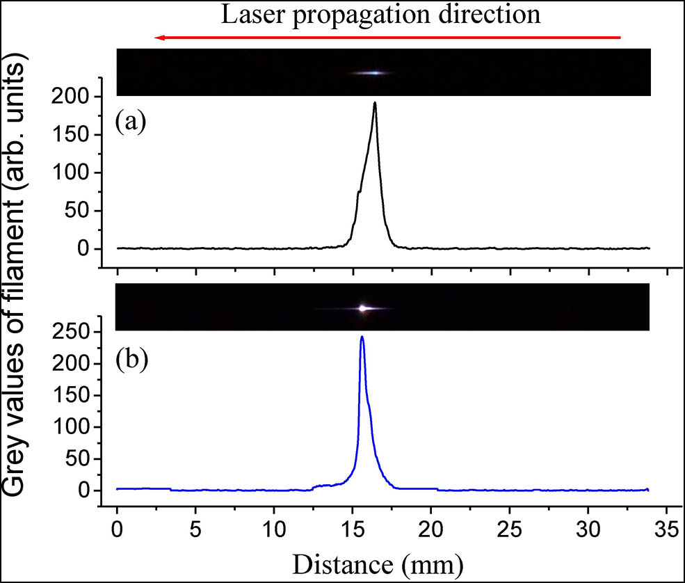
The plasma columns and their corresponding grey values generated by positively and negatively chirped sub-picosecond laser pulses are shown in Figs. 1(a) and 1(b), respectively. The pulse duration was measured at the laser exit. The grey values of the plasma columns were analyzed by ImageJ software, which were transversely integrated. As the images of the plasma columns were captured by a Nikon camera in our experiments, the quantitative results for the intensity inside the plasma column could not be obtained from the profiles, but a qualitative result could be acquired. A higher grey value of the plasma column implies stronger ionization inside the plasma column[13]. It is known that the critical power for self-focusing in air is in the order of a few gigawatts (GW)[25–27]. The peak power is in our experiments. In addition, the Rayleigh range of the focused beam is given by , where the waist spot radius is , calculated from the initial spot size (12 mm in diameter) and the focal length of lens (); is the refractive index of air, for which the Rayleigh range is . The lengths of the plasma columns in Fig. 1 are , which are close to the Rayleigh range. Therefore, the geometric focusing or weak self-focusing is dominant in the formation of the plasma column. It is seen that a bright area with the strongest ionization appears in these two cases, especially for negatively chirped pulses. The intensity of the bright area can be controlled by the chirp value; however, its place does not change with the chirp. This shows that the area with the strongest ionization corresponds to the geometric focus of the lens.

Figure 1.Plasma columns and their corresponding grey values generated by (a) positively and (b) negatively chirped sub-picosecond laser pulses with a pulse duration of (a) and (b) 0.97 ps at a laser power of 6.5 W, respectively. The images of the plasma columns were captured by a camera (Nikon D7000: shutter speed , f number , light sensitivity ).
We also investigated the effects of pulse duration on ionization. The pulse duration was measured at the laser exit. It is found that both the length and the intensity of the plasma column, which initially have a uniform intensity distribution, decrease with the widening of the pulse duration, and then, following this, a brighter ionization area at the focus of the lens appears suddenly inside the plasma column. This strong ionization area becomes the brightest at a certain pulse duration ( and for positive and negative chirps, respectively), and then it becomes weaker and weaker until a short plasma column with a uniform intensity appears again ( for both positive and negative chirps) with the continuous broadening of the pulse duration. With the broadening of the pulse duration, the geometric focusing overwhelms the self-focusing effect. At that time, the intensity is the strongest around the geometric focus inside the plasma column, where the strongest ionization of air occurs. The strong ionization area induced by negatively chirped pulses is always brighter (stronger) than that induced by positively chirped pulses at the same pulse duration. This is not solely due to the group velocity dispersion in the propagation distance, because the increase or decrease of the pulse duration measured to be about 52 fs after the positively or negatively chirped laser pulses propagated from the laser exit to the focus of the lens, respectively. This change of pulse duration is larger than that by the group velocity dispersion in the propagation distance. Besides, the free electrons give rise to anomalous group velocity dispersion[28], which cannot provide the compensation for the propagation of negatively chirped pulse. Self-phase modulation (SPM) in the neutral gas, plasma, and electrons leads to a spectral red/blue shift and (or) broadening/narrowing[29,30]. Spectral broadening or narrowing would make the duration of the output pulse shorter or longer than the initial value, which depends on laser power, nonlinear propagation distance, initial chirp, etc.[30]. Based on our experimental results, the negatively chirped laser pulses probably lead to a broader frequency spectrum followed by shortened pulse duration by SPM. Therefore, the plasma column induced by negatively chirped laser pulses is visibly brighter.
Figures 2(a) and 2(b) show the airflow motion generated by the plasma columns with the positively and negatively chirped laser pulses, respectively. It is found that the velocity of the airflow is much larger (), and a wider range of turbulence is visible for the case of using a negative chirp. Two vortices are generated just below the plasma column. They are similar to the vortices for the 30 fs laser[13,31], but different from those for the 350 ps laser pulses, where the aligned discrete sparks and updraft are induced[22]. This indicates that the filamentation or continuous ionization is the key to the formation of vortices. There is a weak scattering area between the two vortices below the plasma column [the area pointed to by red arrows in Figs. 2(a) and 2(b)], which corresponds to the strongest ionization. Stronger ionization produces more heat release and a stronger shock wave; hence, the airflow with a higher velocity is induced. The high-speed airflow blows the larger-sized particles between the vortices away; therefore, the strong scattering by particles is not observed.
Figure 2.Airflow generated by (a) positively and (b) negatively chirped sub-picosecond laser pulses with a pulse duration of (a) and (b) 0.97 ps at a laser power of 6.5 W, respectively. The images were captured by a Nikon D7000 camera (, , ).
When no laser was shot, the snow formed on the cold plate after an irradiation of 1 h exhibits ramiform structures, as shown in Figs. 3(a) and 3(b), with a size of about 5–8 mm. A small snow pile was produced below the plasma column for both positively and negatively chirped sub-picosecond lasers, as shown in Figs. 4(a) and 4(c), respectively. The shape of the snow pile induced by positively chirped laser pulses is elliptical (the ellipticity of the snow pile is 0.657 rad), and it is round when induced by negatively chirped laser pulses. These results are due to the different diffusions of airflow from the different intensity distributions inside the plasma column. For the plasma column with negative chirp, the strongest ionization area has almost the same size in both the parallel and the perpendicular direction to the plasma column, and so does the induced airflow pattern. Thus, the snow pile formed below the plasma column tends to exhibit a round shape. The structure of the snow particle is also ramiform, as shown in Figs. 4(b) and 4(d), but the sizes decrease significantly compared to the background snow. It is about 1.5 mm for the positively chirped laser pulses, and only for negatively chirped laser pulses. This is because of the stronger ionization inside the plasma column generated by the negatively chirped pulses, which leads to stronger photochemical reactions and higher density aerosols. At the same time, the explosion effect of particles around the plasma column is also enhanced. Therefore, the snow particles formed by negatively chirped pulses are much smaller and denser.
Figure 3.(a) Snow on the cold plate without laser shooting. (b) Close-up view of part of the snow in (a). The shooting conditions of the camera are , , and for (a), , , and for (b).
Figure 4.Snow piles on the cold plate with (a), (b) positively and (c), (d) negatively chirped sub-picosecond laser pulses at a laser power of 6.5 W with a pulse duration of (a), (b) and (c), (d) 0.97 ps, respectively; (b) and (d) are close-up views of (a) and (c). Panels (a), (c) and (b), (d) are in the same scale. The shooting conditions of the camera are , , and for (a), , , and for (b), and , , and for (c) and (d).
We also measured the dependences of the amount of small snow piles below the plasma column and the concentration of in the melted water in the pulse duration, as shown in Fig. 5. The amount of the snow pile decreases with the broadening of the pulse duration, but it is much more for negatively chirped pulses because of the stronger ionization in the plasma column. With the widening of the femtosecond pulse duration to about 1 ps at a fixed average power, the pulse peak intensity decreases step-by-step. Consequently, the amount of snow on the cold bottom plate reduces correspondingly. We deduce that a higher average power but with a lower peak intensity is required for a sub-picosecond laser in order to produce the same snow amount as a femtosecond laser due to the avalanche ionization induced by longer pulses. The concentration of in the melted water was also measured by an ion chromatograph (DionexICS-5000+), which follows the same trend as the amount of the snow piles. The concentration of is in the range from several to tens of parts per million (ppm: mass ratio), depending on the pulse duration, that is, the ionization of the plasma column.
Figure 5.Dependence of the amount of small snow piles below the plasma columns (black circles and red squares, left scale) and concentration of in the melted water (green triangles and blue stars, right scale) in the pulse duration of positively (black circles and green triangles) and negatively chirped pulses (red squares and blue stars), respectively. There is no chirp for the 27 fs pulse duration. The pulse duration was measured at the laser exit.
When an intense laser beam propagates in air, the formed plasma column can ionize or dissociate air molecules and produce high concentrations of in the active volume[9,10], which triggers oxidation reactions of nitrogen and results in the generation of NOx, which finally condenses in the form of or [12]. These hygroscopic and provide major condensation nuclei into a cloud. Meanwhile, intense airflow motion can also be generated after the firing of laser plasma columns into the cloud chamber. The initial CCN around the plasma columns move with air convection-induced mixing and grow into large particles because of the frequent collision in the vortices, where supersaturation is created by mixing air with a large temperature gradient[14,15]. A stronger plasma column generates stronger airflow motion. This accelerates the growing of CCN and produces more snow precipitation. More snow formation also increases the release of latent heat of condensation, which can further accelerate the airflow mixing[32].
In summary, we investigated sub-picosecond chirped laser pulse-induced airflow and water condensation in an experimental diffusion cloud chamber. The control of the airflow and water condensation can be realized by adjusting the intensity distribution inside the plasma column by using positively and negatively chirped laser pulses. The positively chirped sub-picosecond laser pulse generates a more uniform intensity distribution inside the plasma column. This leads to a weaker airflow and an elliptic-shaped snow pile. The negatively chirped sub-picosecond laser pulse produces a spark-like intensity distribution inside the plasma column, which results in a stronger diffusion airflow and a round snow pile. Both the amount of snow weight and the concentration of in the melted water decrease with the broadening of the pulse duration regardless of the positively or negatively chirped laser pulse. However, the amount of snow weight and the concentration of in the melted water are much larger in the case of the negatively chirped laser pulses because of the stronger ionization in the plasma column. Picosecond laser systems have simpler construction and higher stability, as well as higher output power developed in recent years, which probably provide an alternative way for the application of laser-induced water condensation in realistic atmospheric conditions.
References
[1] V. J. Schaefer. Science, 104, 457(1946).
[2] I. Langmuir. Science, 106, 505(1947).
[3] V. J. Schaefer. Science, 112, 447(1950).
[4] P. Rohwetter, J. Kasparian, K. Stelmaszczyk, Z. Hao, S. Henin, N. Lascoux, W. M. Nakaema, Y. Petit, M. Queißer, R. Salamé, E. Salmon, L. Wöste, J.-P. Wolf. Nat. Photon., 4, 451(2010).
[5] S. Henin, Y. Petit, P. Rohwetter, K. Stelmaszczyk, Z. Q. Hao, W. M. Nakaema, A. Vogel, T. Pohl, F. Schneider, J. Kasparian, K. Weber, L. Wöste, J.-P. Wolf. Nat. Commun., 2, 456(2011).
[6] T. Leisner, D. Duft, O. Möhler, H. Saathoff, M. Schnaiter, S. Henin, K. Stelmaszczyk, M. Petrarca, R. Delagrange, Z. Hao, J. Lüde, Y. Petit, P. Rohwetter, J. Kasparian, J.-P. Wolf, L. Wöste. PNAS, 110, 10106(2013).
[7] J. Ju, J. Liu, C. Wang, H. Sun, W. Wang, X. Ge, C. Li, S. L. Chin, R. Li, Z. Xu. Opt. Lett., 37, 1214(2012).
[8] H. Sun, J. Liu, C. Wang, J. Ju, Z. Wang, W. Wang, X. Ge, C. Li, S. L. Chin, R. Li, Z. Xu. Opt. Express, 21, 9255(2013).
[9] Y. Petit, S. Henin, J. Kasparian, J.-P. Wolf. Appl. Phys. Lett., 97, 021108(2010).
[10] P. Rohwetter, J. Kasparian, L. Wöste, J.-P. Wolf. J. Chem. Phys., 135, 134703(2011).
[11] H. Saathoff, S. Henin, K. Stelmaszczyk, M. Petrarca, R. Delagrange, Z. Hao, J. Lüder, O. Möhler, Y. Petit, P. Rohwetter, M. Schnaiter, J. Kasparian, T. Leisner, J.-P. Wolf, L. Wöste. Atmos. Chem. Phys., 13, 4593(2013).
[12] D. Mongin, J. G. Slowik, E. Schubert, J.-G. Brisset, N. Berti, M. Moret, A. S. H. Prévôt, U. Baltensperger, J. Kasparian, J.-P. Wolf. Sci. Rep., 5, 14978(2015).
[13] H. Sun, H. Liang, Y. Liu, J. Ju, Y. Wei, C. Wang, T. Wang, J. Liu, S. L. Chin, R. Li, Z. Xu. Appl. Phys. B, 121, 155(2015).
[14] J. Ju, H. Sun, A. Sridharan, T. Wang, C. Wang, J. Liu, R. Li, Z. Xu, S. L. Chin. Phys. Rev. E, 88, 062803(2013).
[15] J. Ju, T. Leisner, H. Sun, A. Sridharan, T. Wang, J. Wang, C. Wang, J. Liu, R. Li, Z. Xu, S. L. Chin. Appl. Phys. B, 117, 1001(2014).
[16] I. S. Golubtsov, V. P. Kandidov, O. G. Kosareva. Quantum Electron., 33, 525(2003).
[17] G. Méchain, C. D’Amico, Y.-B. André, S. Tzortzakis, M. Franco, B. Prade, A. Mysyrowicz, A. Couairon, E. Salmon, R. Sauerbrey. Opt. Commun., 247, 171(2005).
[18] F. Courvoisier, V. Boutou, J. Kasparian, E. Salmon, G. Méjean, J. Yu, J.-P. Wolf. Appl. Phys. Lett., 83, 213(2003).
[19] R. Salamé, N. Lascoux, E. Salmon, J. Kasparian, J. P. Wolf. Appl. Phys. Lett., 91, 171106(2007).
[20] G. Méjean, J. Kasparian, J. Yu, E. Salmon, S. Frey, J.-P. Wolf, S. Skupin, A. Vinçotte, R. Nuter, S. Champeaux, L. Bergé. Phys. Rev. E, 72, 026611(2005).
[21] S. Henin, Y. Petit, J. Kasparian, J.-P. Wolf, A. Jochmann, S. D. Kraft, S. Bock, U. Schramm, R. Sauerbrey, W. M. Nakaema, K. Stelmaszczyk, P. Rohwetter, L. Wöste, C.-L. Soulez, S. Mauger, L. Bergé, S. Skupin. Appl. Phys. B, 100, 77(2010).
[22] H. Sun, Y. Liu, J. Ju, Y. Tian, Y. Bai, Y. Liu, S. Du, C. Wang, T. Wang, J. Liu, S. L. Chin, R. Li, Z. Xu. Opt. Express, 24, 20494(2016).
[23] F. Courvoisier, V. Boutou, C. Favre, S. C. Hill, J.-P. Wolf. Opt. Lett., 28, 206(2003).
[24] A. Schmitt-Sody, H. G. Kurz, L. Bergé, S. Skupin, P. Polynkin. New J. Phy., 18, 093005(2016).
[25] V. P. Kandidov, S. A. Shlenov, O. G. Kosareva. Quantum Electron., 39, 205(2009).
[26] V. Loriot, E. Hertz, O. Faucher, B. Lavorel. Opt. Express, 17, 13429(2009).
[27] W. Liu, S. L. Chin. Opt. Express, 13, 5750(2005).
[28] P. Sprangle, E. Esarey, B. Hafizi. Phys. Rev. Lett., 79, 1046(1997).
[29] S. L. Chin, S. A. Hosseini, W. Liu, Q. Luo, F. Théberge, N. Aközbek, A. Becker, V. P. Kandidov, O. G. Kosareva, H. Schroeder. Can. J. Phys., 83, 863(2005).
[30] S. A. Planas, N. L. Pires Mansur, C. H. Brito Cruz, H. L. Fragnito. Opt. Lett., 18, 699(1993).
[31] Y. Liu, H. Sun, J. Ju, Y. Tian, Y. Bai, C. Wang, T. Wang, J. Liu, S. L. Chin, R. Li. Chin. Opt. Lett., 14, 031401(2016).
[32] R. L. Armstrong, E. Brun. Snow and Climate: Physical Processes, Surface Energy Exchange and Modelling(2008).