• NUCLEAR TECHNIQUES
  • Vol. 47, Issue 1, 010404 (2024)
Zhongbin HANG1, Yuntao LIU1, Mingzhe SONG1、*, Kexin WEI1, Hongyu WANG1, Chuanfeng LIU2, Zhongbin TENG1, and Xuan GENG1
Author Affiliations
  • 1Key Laboratory of Measurement and Calibration Technology, China Institute of Atomic Energy, Beijing 102413, China
  • 2National Institute of Metrology, Beijing 100029, China
  • show less
    DOI: 10.11889/j.0253-3219.2024.hjs.47.010404 Cite this Article
    Zhongbin HANG, Yuntao LIU, Mingzhe SONG, Kexin WEI, Hongyu WANG, Chuanfeng LIU, Zhongbin TENG, Xuan GENG. Simulation of internal electric field of particle source water absorbed dose absolute measurement device[J]. NUCLEAR TECHNIQUES, 2024, 47(1): 010404 Copy Citation Text show less
    Structure diagram of the short-range particle source water absorbed dose absolute measurement ionization chamber
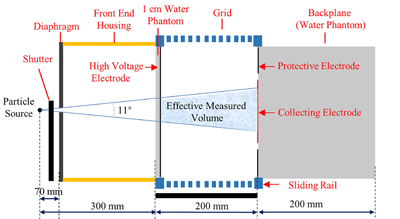
    Fig. 1. Structure diagram of the short-range particle source water absorbed dose absolute measurement ionization chamber
    Internal structure of the ionization chamber under Maxwell software
    Fig. 2. Internal structure of the ionization chamber under Maxwell software
    Electric field diagram with and without guard ring(a) Without protective electrode, (b) With protective electrode
    Fig. 3. Electric field diagram with and without guard ring(a) Without protective electrode, (b) With protective electrode
    Variation of electric field change with or without protective electrode
    Fig. 4. Variation of electric field change with or without protective electrode
    Electric field diagrams of different guard electrode widths (high voltage electrode remains unchanged)(a) 9 mm, (b) 29 mm, (c) 49 mm, (d) 69 mm, (e) 89 mm, (f) 109 mm
    Fig. 5. Electric field diagrams of different guard electrode widths (high voltage electrode remains unchanged)(a) 9 mm, (b) 29 mm, (c) 49 mm, (d) 69 mm, (e) 89 mm, (f) 109 mm
    Electric field changes with different guard electrode widths under invariant high voltage electrodes (color online)
    Fig. 6. Electric field changes with different guard electrode widths under invariant high voltage electrodes (color online)
    Electric field diagrams of different guard electrode widths (high voltage electrode keeps the same outer diameter as guard electrode) (a) 9 mm, (b) 29 mm, (c) 49 mm, (d) 69 mm, (e) 89 mm, (f) 109 mm
    Fig. 7. Electric field diagrams of different guard electrode widths (high voltage electrode keeps the same outer diameter as guard electrode) (a) 9 mm, (b) 29 mm, (c) 49 mm, (d) 69 mm, (e) 89 mm, (f) 109 mm
    Electric field changes with different guard electrode widths while high voltage electrode keeps the same outer diameter as the guard electrode (color online)
    Fig. 8. Electric field changes with different guard electrode widths while high voltage electrode keeps the same outer diameter as the guard electrode (color online)
    Electric field diagrams of different insulating ring widths (a) 1 mm, (b) 3 mm, (c) 5 mm, (d) 7 mm, (e) 9 mm
    Fig. 9. Electric field diagrams of different insulating ring widths (a) 1 mm, (b) 3 mm, (c) 5 mm, (d) 7 mm, (e) 9 mm
    Electric field variation with different insulating ring widths (color online)
    Fig. 10. Electric field variation with different insulating ring widths (color online)
    Electric field diagrams with different numbers of grid electrode (a) 0, (b) 1, (c) 3, (d) 7, (e) 15
    Fig. 11. Electric field diagrams with different numbers of grid electrode (a) 0, (b) 1, (c) 3, (d) 7, (e) 15
    Electric field variation with different grid electrode numbers (color online)
    Fig. 12. Electric field variation with different grid electrode numbers (color online)
    Schematic diagram of different grid shapes
    Fig. 13. Schematic diagram of different grid shapes
    Electric field diagrams for different grid shapes(a) Rectangle, (b) Round, (c) Triangle
    Fig. 14. Electric field diagrams for different grid shapes(a) Rectangle, (b) Round, (c) Triangle
    Electric field variation for different grid shapes (color online)
    Fig. 15. Electric field variation for different grid shapes (color online)
    Electric field diagrams for different gate widths (a) 2 mm, (b) 5 mm, (c) 10 mm, (d) 20 mm
    Fig. 16. Electric field diagrams for different gate widths (a) 2 mm, (b) 5 mm, (c) 10 mm, (d) 20 mm
    Electric field variation for different gate widths (color online)
    Fig. 17. Electric field variation for different gate widths (color online)
    不变量项目Invariant参数 Parameter
    收集极厚度 Collector thickness0.01 mm
    高压极厚度 Thickness of high-voltage electrode0.01 mm
    两极板间距 Distance between two plates200 mm
    收集极半径 Radius of collecting electrode50 mm
    高压极半径 Radius of high-voltage electrode100 mm
    保护极外径 Outer diameter of protective electrode100 mm
    高压极电压 High voltage electrode voltage2 kV
    收集极电压 Collector voltage0 V
    Table 1. Partial simulation parameters
    Zhongbin HANG, Yuntao LIU, Mingzhe SONG, Kexin WEI, Hongyu WANG, Chuanfeng LIU, Zhongbin TENG, Xuan GENG. Simulation of internal electric field of particle source water absorbed dose absolute measurement device[J]. NUCLEAR TECHNIQUES, 2024, 47(1): 010404
    Download Citation