• Acta Photonica Sinica
  • Vol. 50, Issue 12, 1212001 (2021)
Huijun YU1、2, Xiaoguang LI2, and Wenjiang SHEN2、*
Author Affiliations
  • 1School of Nano-tech and Nano-bionics, University of Science and Technology of China, Hefei 230026, China
  • 2Key Lab of Nanodevices and Applications, Suzhou Institute of Nano-tech and Nano-bionics, Chinese Academy of Sciences , Suzhou , Jiangsu 215123, China
  • show less
    DOI: 10.3788/gzxb20215012.1212001 Cite this Article
    Huijun YU, Xiaoguang LI, Wenjiang SHEN. Scanning Angle Compensation of MEMS Mirror Applied in Monocular 3D Camera[J]. Acta Photonica Sinica, 2021, 50(12): 1212001 Copy Citation Text show less
    The basic structure of MEMS micromirror with integrated piezoresistive sensor
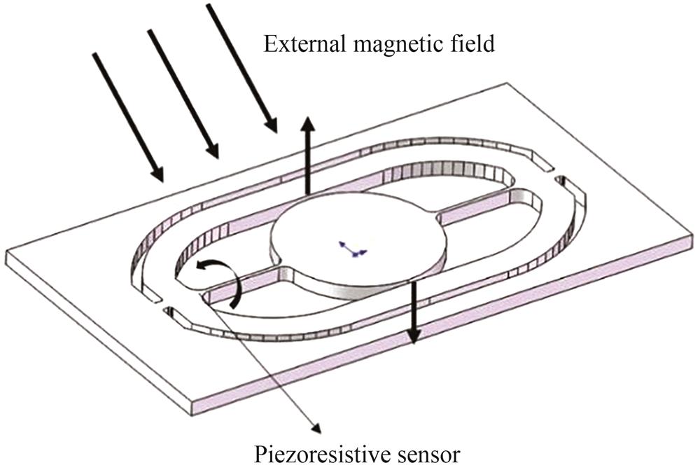
    Fig. 1. The basic structure of MEMS micromirror with integrated piezoresistive sensor
    Crystal orientation of piezoresistive element and torsion beam
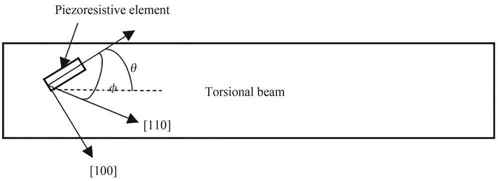
    Fig. 2. Crystal orientation of piezoresistive element and torsion beam
    The relationship between piezoresistive coefficient and impurity concentrations
    Fig. 3. The relationship between piezoresistive coefficient and impurity concentrations
    Projection optical engine and projection stripe pattern
    Fig. 4. Projection optical engine and projection stripe pattern
    Monocular 3D camera measures the distance between the camera and the white wall(open-loop control MEMS scanner)
    Fig. 5. Monocular 3D camera measures the distance between the camera and the white wall(open-loop control MEMS scanner)
    The relationship between the FOV and the temperature (open-loop control)
    Fig. 6. The relationship between the FOV and the temperature (open-loop control)
    Measure system of the piezoresistive sensor performance
    Fig. 7. Measure system of the piezoresistive sensor performance
    Output amplitude of piezoresistive sensor at different scan angle FOV(input voltage 3.3 V)
    Fig. 8. Output amplitude of piezoresistive sensor at different scan angle FOV(input voltage 3.3 V)
    Piezoresistive output and temperature calibration system
    Fig. 9. Piezoresistive output and temperature calibration system
    The relationship between the piezoresitive output amplitude and the temperature
    Fig. 10. The relationship between the piezoresitive output amplitude and the temperature
    The control logic block diagram of scanning angle of MEMS micromirror
    Fig. 11. The control logic block diagram of scanning angle of MEMS micromirror
    The relationship between the FOV of MEMS scanning angle and the temperature (open-loop control and closed-loop control)
    Fig. 12. The relationship between the FOV of MEMS scanning angle and the temperature (open-loop control and closed-loop control)
    Monocular 3D camera
    Fig. 13. Monocular 3D camera
    Monocular 3D camera measures the distance between the camera and the white wall
    Fig. 14. Monocular 3D camera measures the distance between the camera and the white wall
    Torsional beam alone the <110> directionTorsional beam alone the <100> direction
    p-typen-typep-typen-type
    π116.6-102.26.6-102.2
    π12-1.153.4-1.153.4
    π44138.1-13.6138.1-13.6
    θ45°45°
    ϕ45°45°45°45°
    Coefficient7.70-155.60138.1-13.6
    Table 1. The calculated results of the piezoresistive coefficients
    Huijun YU, Xiaoguang LI, Wenjiang SHEN. Scanning Angle Compensation of MEMS Mirror Applied in Monocular 3D Camera[J]. Acta Photonica Sinica, 2021, 50(12): 1212001
    Download Citation