
Ben LI, Jingfeng ZHOU, Yi WANG, Yang BAI. Finite Element Thermal Analysis of Optical Lenses in 10 kW Rectangular Spot Laser Space Combiner[J]. Acta Photonica Sinica, 2022, 51(2): 0251213
- Acta Photonica Sinica
- Vol. 51, Issue 2, 0251213 (2022)
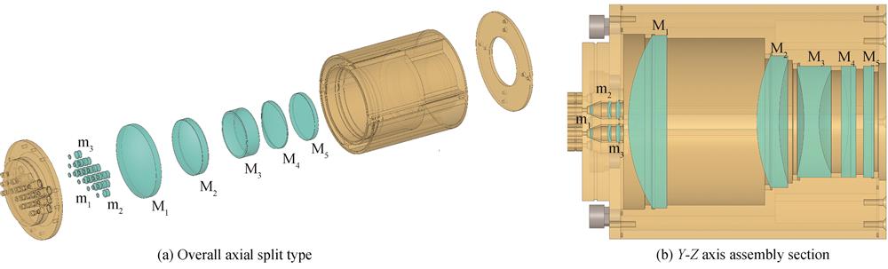
Fig. 1. Engineering 3D design drawing of combiner
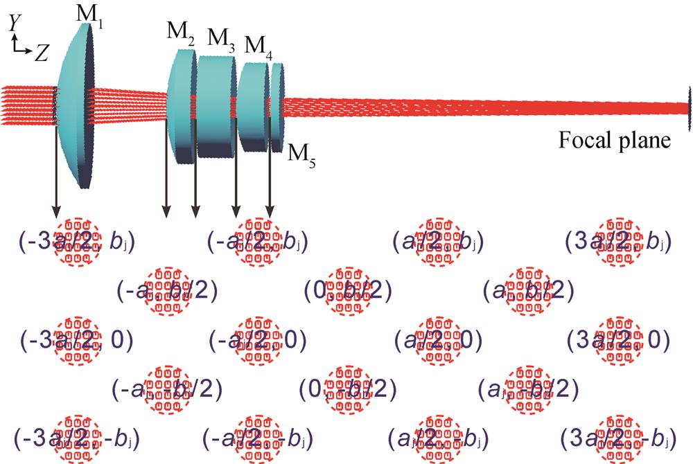
Fig. 2. Spot center coordinates of 18 laser beams on the incident surface of the M1 lens
Fig. 3. Simulated temperature distribution on incident surface,exit surface and central section of the lens M1 to M5 at the 10 kW laser beam combining time of 1 000 s
Fig. 4. Maximum temperature change law in the lens M1 to M5 varying within 1 000 s of the 10 kW combined laser irradiation
Fig. 5. Simulated thermal deformation distribution on incident surface,exit surface and central section of the lens M1 to M5 at the 10 kW laser beam combining time of 1 000 s
Fig. 6. Maximum thermal deformation law in the lens M1 to M5 varying within 1 000 s of the 10 kW combined laser irradiation
Fig. 7. Simulated thermal stress distribution on incident surface,exit surface and central section of the lens M1 to M5 at the 10 kW laser beam combining time of 1 000 s
Fig. 8. Maximum thermal stress law in the lens M1 to M5 varying within 1 000 s of the 10 kW combined laser irradiation
Fig. 9. Physical photo of the combiner
Fig. 10. Center temperature test photos on the exit surface of the lens M5 during 10 kW laser beam combining period of 1 000 s using a thermal imager
Fig. 11. Measurement curve and simulation curve of the center temperature on the exit surface of lens M5 during the 10 kW laser beam combining period of 1 000 s
|
Table 1. Parameters of lenses in space incoherent beam combiner
|
Table 2. Transmission parameters of the laser beams through the optical lenses in space combining
|
Table 3. Thermo-physical properties of fused silica glass
|
Table 4. Thermo-mechanical properties of optical lenses in combiner

Set citation alerts for the article
Please enter your email address
© Copyright 2018-2021 | Chinese Laser Press. All Rights Reserved 沪ICP备15018463号-20