• NUCLEAR TECHNIQUES
  • Vol. 45, Issue 11, 110601 (2022)
Siqin HU1、2, Jian TIAN1、*, Chong ZHOU1, Yang ZOU1, and Xiaohan YU1
Author Affiliations
  • 1Shanghai Institute of Applied Physics, Chinese Academy of Sciences, Shanghai 201800, China
  • 2University of Chinese Academy of Sciences, Beijing 100049, China
  • show less
    DOI: 10.11889/j.0253-3219.2022.hjs.45.110601 Cite this Article
    Siqin HU, Jian TIAN, Chong ZHOU, Yang ZOU, Xiaohan YU. Optimal design of core flow distribution for 10 MW liquid fuel molten salt reactor[J]. NUCLEAR TECHNIQUES, 2022, 45(11): 110601 Copy Citation Text show less
    Vertical section (a) and cross section (b) of 10 MW molten salt reactor-liquid fuel
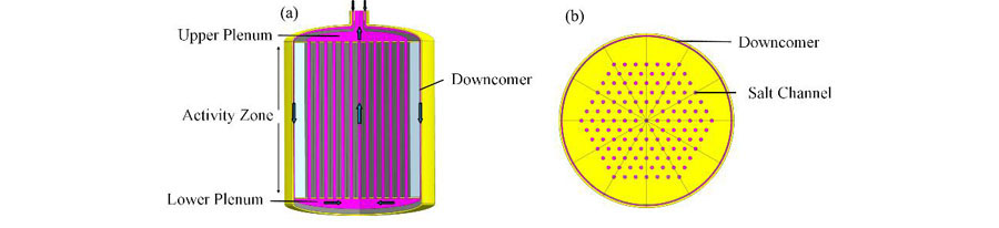
    Fig. 1. Vertical section (a) and cross section (b) of 10 MW molten salt reactor-liquid fuel
    Diagram of 1/12 molten salt channels model of reactor core
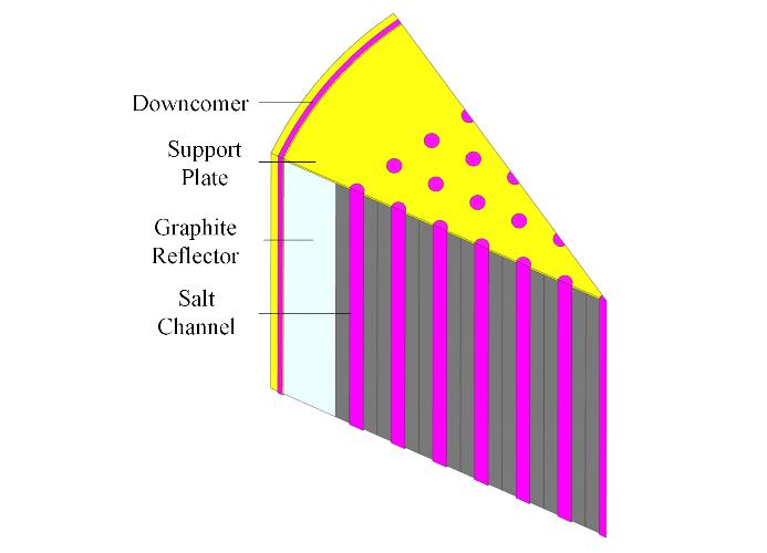
    Fig. 2. Diagram of 1/12 molten salt channels model of reactor core
    Relationship between channels mass flow rate and mesh elements number
    Fig. 3. Relationship between channels mass flow rate and mesh elements number
    Channel mass flow rate corresponding to different turbulent model
    Fig. 4. Channel mass flow rate corresponding to different turbulent model
    Channel mass flow rate distribution factor corresponding to different heights of the upper plenum
    Fig. 5. Channel mass flow rate distribution factor corresponding to different heights of the upper plenum
    Channel mass flow rate distribution factor corresponding to different widths of the downcomer
    Fig. 6. Channel mass flow rate distribution factor corresponding to different widths of the downcomer
    Streamline distribution diagram of lower plenum with different thickness D (a) D=10 mm, (b) D=20 mm, (c) D=30 mm, (d) D=40 mm
    Fig. 7. Streamline distribution diagram of lower plenum with different thickness D (a) D=10 mm, (b) D=20 mm, (c) D=30 mm, (d) D=40 mm
    Channel mass flow rate distribution factor corresponding to different geometry structure of the down plenum
    Fig. 8. Channel mass flow rate distribution factor corresponding to different geometry structure of the down plenum
    Diagram of shroud in the lower plenum (a) and vertical section (b)
    Fig. 9. Diagram of shroud in the lower plenum (a) and vertical section (b)
    Mass flow rate distribution factor corresponding to different the geometry structure of the shroud
    Fig. 10. Mass flow rate distribution factor corresponding to different the geometry structure of the shroud
    Comparison of velocity field distribution in the lower plenum after adding shroud with solution case 0 (a) and case 1 (b)
    Fig. 11. Comparison of velocity field distribution in the lower plenum after adding shroud with solution case 0 (a) and case 1 (b)
    Comparison of mass flow rate distribution factor with different solutions (case 0~4)
    Fig. 12. Comparison of mass flow rate distribution factor with different solutions (case 0~4)
    Comparison of streamline distribution in lower plenum with different solutions (a) Case 0, (b) Case 1, (c) Case 2, (d) Case 3, (e) Case 4
    Fig. 13. Comparison of streamline distribution in lower plenum with different solutions (a) Case 0, (b) Case 1, (c) Case 2, (d) Case 3, (e) Case 4
    设计参数 Design parameter值Value
    活性区直径(含反射层)Diameter of active zone (including reflector) / m2.8
    熔盐孔道直径 Diameter of salt channel / m0.06
    熔盐通道个数 Number of channels127
    活性区高度 Height of activity zone / m3
    燃料盐 Fuel saltLiF-BeF2-ZrF4-UF4-ThF
    Table 1. Design parameters
    边界条件Boundary condition参数Value
    湍流模型Turbulent model标准k-ε Standard k-ε
    进口质量流量Inlet Mass flow rate / kg·s-126.25
    进出口水力直径Inlet/outlet hydraulic diameter / m0.2
    进出口流速 Inlet/outlet velocity / m·s-11.1
    进口管道雷诺数Reynolds88 000
    出口压力Pressure outlet / Pa0
    壁面条件Wall condition光滑壁面,无滑移条件Smooth wall, no-slip boundary condition
    Table 2. Calculation conditions

    方案编号

    Number

    结构变化

    Change of structure

    匹配因子标准差

    Standard deviation of matching factor / %

    05.16
    1

    设置导流围筒,下支撑板孔径尺寸与活性区通道尺寸一致

    With a shroud, the size of holes on support plate is consistent with the channel in the active zone

    4.33
    2

    设置导流围筒,缩减第2、3、4圈孔直径为55 mm,第5、6、7圈为50 mm

    With a shroud, changeable diameter of holes on support plate (55 mm for the 2nd , 3rd and 4th loop, 50 mm for the 5th, 6th and 7th loop)

    4.14
    Table 3. Optimization schemes
    方案编号Number结构改变Structure changes匹配因子标准差Standard deviation of matching factor / %
    0初始结构Primary structure30.7
    1增高上腔室高度至200 mm Increase height of upper plenum to 200 mm24.21
    2增加下降环腔宽度至30 mm Increase width of downcomer to 30 mm10.55
    3

    下腔室改为圆柱形,高度调整为100 mm

    Change the lower plenum to cylindrical, change the height to 100 mm

    5.16
    4

    下腔室增设导流围筒,调整下支撑板孔径

    Set the shroud in lower plenum, change the size of holes on support plate

    4.14
    Table 4. Schemes of flow distribution
    Siqin HU, Jian TIAN, Chong ZHOU, Yang ZOU, Xiaohan YU. Optimal design of core flow distribution for 10 MW liquid fuel molten salt reactor[J]. NUCLEAR TECHNIQUES, 2022, 45(11): 110601
    Download Citation